
Real-time-optical-projection-based vehicle camouflage apparatus and method

An optical projection and vehicle technology, which is applied in the direction of image reproducer, optics and projection device using projection device, can solve the problems of high price, high production cost, high cost, etc., and achieves cost reduction, simple structure and easy operation Simple and practical effects

Inactive Publication Date: 2017-03-22
BEIJING INST OF SPACE LAUNCH TECH +2
View PDF3 Cites 7 Cited by
  • Summary
  • Abstract
  • Description
  • Claims
  • Application Information

AI Technical Summary

Problems solved by technology

In 2012, Canadian researchers announced that they had developed a "quantum invisibility cloak", but at present, the world's largest can only realize the invisibility of a 5-inch-sized object, and this material has not been mass-produced so far, and it is expensive, and cannot be invisible such as vehicles. There are no specific application reports for large objects such as large objects. Another optical camouflage method that has been studied more is to install an LED screen on the target that needs to be camouflaged. Blocked background images for stealth purposes
This optical camouflage method needs to install a large-area LED display on the surface of the hidden target. If you choose a mature and low-cost LED hard screen, it is difficult to completely cover the surface of the curved car body. The process technology is currently immature, the production cost is high, and the price is expensive, which limits its development and application in vehicle stealth

Method used


Image

  • Real-time-optical-projection-based vehicle camouflage apparatus and method
  • Real-time-optical-projection-based vehicle camouflage apparatus and method
  • Real-time-optical-projection-based vehicle camouflage apparatus and method

Examples


Embodiment Construction

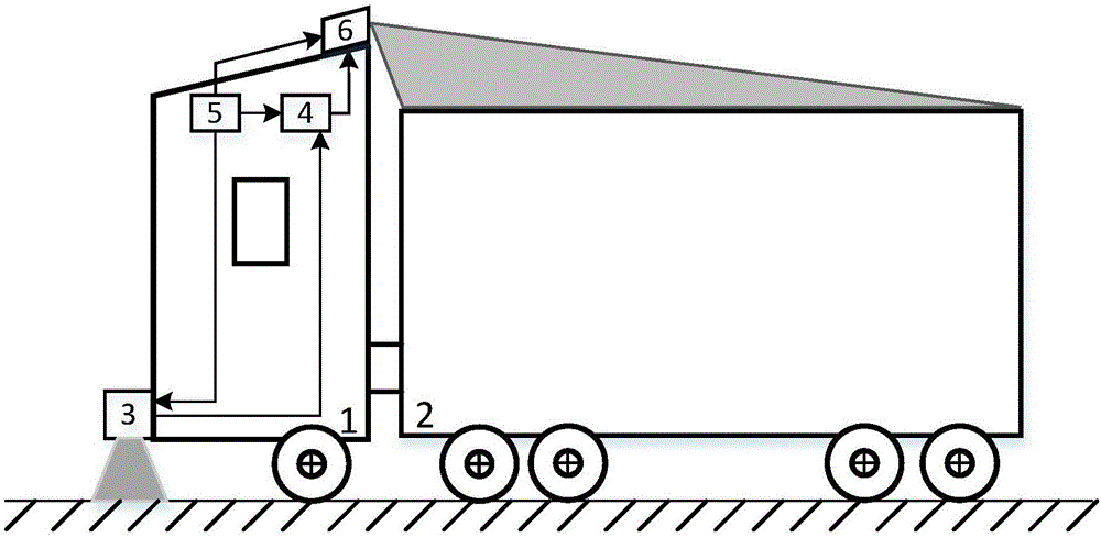
[0022] The vehicle camouflage device based on real-time optical projection in the present invention is installed on the vehicle for use, such as figure 1 As shown, the vehicle includes a headstock 1 and a compartment 2 connected to each other. The vehicle camouflage device based on real-time optical projection in the present invention includes an optical image acquisition module 3, an image processing module 4, an optical projection module 6 and a power supply 5. The optical image The acquisition module 3 is used to be arranged at the front and bottom of the vehicle head 1, the image processing module 4 and the power supply 5 are used to be arranged inside the vehicle, and the optical projection module 6 is used to be arranged at the top rear of the vehicle head 1, so The output port of the optical image acquisition module 3 is connected to the input port of the image processing module 4, the output port of the image processing module 4 is connected to the input port of the opt...


PUM


Abstract

The invention relates to an optical cloaking device and method, especially to a real-time-optical-projection-based vehicle camouflage apparatus and method. The invention aims at providing a real-time-optical-projection-based vehicle camouflage apparatus and method, thereby realizing special vehicle camouflage under satellite monitoring or unmanned aerial vehicle aerial shooting and thus realizing effective cloaking. The vehicle camouflage apparatus comprises an optical image acquisition module (3), an image processing module (4), an optical projection module (6) and a power supply (5). In addition, the vehicle camouflage method includes the following steps that: step a, the optical image acquisition module (3) collects pavement and ambient environment background images in a vehicle driving direction and transmits the images to the image processing module (4); step b, the image processing module processes the background images and then transmits the processed images to the optical projection module (6); and step c, the optical projection module projects the processed images on the top of a carriage (2).

Description

technical field [0001] The invention relates to an optical cloaking device and method for vehicles, in particular to an active projection-based optical cloaking device and method. Background technique [0002] Optical stealth is a new type of stealth technology. Traditional optical stealth methods usually cover the battlefield with plants to integrate the surface of the device with the environment. However, the disadvantage is that when the device moves, due to changes in the surrounding environment, the It will cause the camouflage used to be inconsistent with the surrounding environment and be exposed. [0003] One of the current international research directions on stealth technology is the development of "negative refractive index" stealth materials, which can make light travel along curves and bypass objects, thereby making the target "disappear". In 2012, Canadian researchers announced that they had developed a "quantum invisibility cloak", but at present, the world's...

Claims


Application Information

Patent Timeline
Patent Type & Authority Applications(China)
IPC IPC(8): H04N9/31G03B21/00
CPCH04N9/3185G03B21/00H04N9/3188
Inventor 王丽伟黎兰王焕钦顾乃威聂余满杭立杰余慧娟刘琥孙颖力卢卫建韦学中
Owner BEIJING INST OF SPACE LAUNCH TECH
Learn More