Liquefied gas treatment system

A processing system and technology for liquefied gas, applied in liquefaction, gas processing/storage effect, fluid processing, etc., can solve problems such as different states, and achieve the effects of preventing accumulation, improving reliquefaction efficiency, and improving driving efficiency

A processing system and technology for liquefied gas, applied in liquefaction, gas processing/storage effect, fluid processing, etc., can solve problems such as different states, and achieve the effects of preventing accumulation, improving reliquefaction efficiency, and improving driving efficiency

CN106537023AActive Publication Date: 2017-03-22HYUNDAI HEAVY IND CO LTD

Image

  • Liquefied gas treatment system
  • Liquefied gas treatment system
  • Liquefied gas treatment system

Examples


Embodiment approach

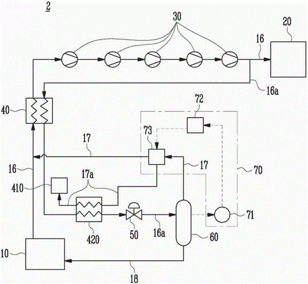
[0100] Such as image 3 As shown, the liquefied gas treatment system 2 of the second embodiment of the present invention includes a liquefied gas storage tank 10, a demand source 20, a boil-off gas compressor 30, a boil-off gas heat exchanger 40, a boil-off gas liquefier 50, a steam-liquid Separator 60 , nitrogen control unit 70 , consumption source 410 , and flash gas heat exchanger 420 . Compared with the first embodiment of the present invention, the second embodiment of the present invention has a different configuration of the consumption source 410 and the flash gas heat exchanger 420, and the connection relationship of the steam processing pipeline 17a related to this configuration is also different. For the sake of convenience, components identical to or corresponding to those in the first embodiment of the present invention are denoted by similar symbols, and repeated description thereof will be omitted.

[0101] The consumption source 410 may be a gas combustion un...


PUM


Abstract

The present invention relates to a liquefied gas treatment system in which a nitrogen control unit controls the content of nitrogen in a boil-off gas or a flash gas when nitrogen components of the flash gas are greater than or equal to a preset value. The efficiency of a boil-off gas compressor can be improved and the system can be stabilized by means of the nitrogen control unit.

Description

technical field [0001] The invention relates to a liquefied gas processing system. Background technique [0002] With recent technological progress, liquefied gas such as liquefied natural gas or liquefied petroleum gas has recently been widely used instead of gasoline or diesel. [0003] Liquefied natural gas is a gas that is converted into a liquid state by cooling methane obtained from the refining of natural gas extracted from gas fields. Liquefied natural gas is a colorless and transparent liquid, is a very good fuel, almost no pollution, and has a high calorific value. Liquefied petroleum gas, on the other hand, is produced by extracting oil from oil fields, mainly from propane (C 3 h 8 ) and butane (C 4 h 10 ) is a fuel produced by compressing a gas composed of ) into a liquid state at room temperature. Like liquefied natural gas, liquefied petroleum gas is colorless and odorless, and is widely used as a fuel for domestic, commercial, industrial and automotive a...

Claims


Application Information

Patent Timeline
22 Mar 2017
Publication
CN106537023A
IPC
F17C7/04; B63B25/16; B63H21/38
CPC
F25J1/004; F25J1/0202; F25J1/023; F25J1/0244; F25J2220/62; F17C2221/033; F17C2223/0161; F17C2265/033
Inventors
李振光; 李相奉