
A self-excited retarder with a double-rotor structure and its control method

A retarder and dual-rotor technology, applied in electric braking systems, vehicle components, electric vehicles, etc., can solve the problem that the retarder braking torque is not adjustable, cannot fully utilize the dual-rotor disc, and cannot generate Braking torque and other problems, to achieve the effect of solving thermal recession, continuous braking force, and expanding range

Active Publication Date: 2019-02-05
徐州市通途装配式建筑科技有限公司
View PDF7 Cites 0 Cited by
  • Summary
  • Abstract
  • Description
  • Claims
  • Application Information

AI Technical Summary

Problems solved by technology

However, in order to make the retarder have a good heat dissipation effect, there are centrifugal air ducts on the double rotor discs, so magnetic flux leakage will inevitably occur, which reduces the braking torque during auxiliary braking and cannot fully Give full play to the role of the dual rotor discs; in addition, the dual rotor discs must act at the same time, and one rotor disc cannot independently generate braking torque according to the auxiliary braking requirements, and the braking torque of the retarder is not adjustable
[0005] The Chinese patent application number is 201210061808.1, and the retarder disclosed in the document titled "A Liquid-cooled Self-excited Eddy Current Retarder with Salient Structure", the coil is fixed inside the stator, which reduces the area of ​​the water channel and is not conducive to heat dissipation , and the coil needs to be separated from the retarder rotor

Method used

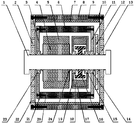
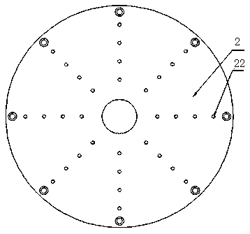
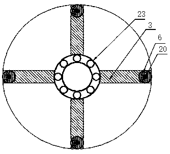

Image

  • A self-excited retarder with a double-rotor structure and its control method
  • A self-excited retarder with a double-rotor structure and its control method
  • A self-excited retarder with a double-rotor structure and its control method

Examples


Embodiment Construction

[0024] see figure 1 The self-excited retarder of the present invention has a transmission shaft 1, a left side housing 2 and a right side housing 13, and the left side housing 2 and the right side housing 13 are respectively coaxially sleeved on the left end and the right end of the transmission shaft 1 , and is fixedly connected with the transmission shaft 1. Between the radially outer edges of the left casing 2 and the right casing 13 , the outer rotor 8 is fixedly connected by first screws 9 . Salient poles are arranged on the inner side of the outer rotor 8 . The salient poles are arranged radially inward, and the outer rotor excitation coils 7 are wound on the salient poles. An outer rotor magnetic plate 10 is respectively connected between the left and right ends of the outer rotor 8 and the left casing 2 and the right casing 13 .

[0025] A left stator support 3 and a right stator support 11 are also arranged between the left housing 2 and the right housing 13, wherei...


PUM


Abstract

The invention discloses a self-excitation type retarder adopting a double-rotor structure and a control method of the self-excitation type retarder, and the self-excitation type retarder is arranged on an automobile. An outer rotor excitation coil is wound around the inner side face of an outer rotor, and a retarder stator is coaxially sleeved with the outer rotor. An inner rotor and a retarder power generation device are coaxially sleeved with the retarder stator. The inner rotor and the retarder power generation device are arranged left and right in the axial direction and coaxially connected with a transmission shaft. An inner rotor excitation coil is wound around the outer side face of the inner rotor. The retarder power generation device is composed of a power generation device shell, a power generation device coil and a permanent magnet. A master controller calculates the braking strength according to a braking signal sent by a brake pedal displacement sensor, the manner adopted for braking is judged, the transmission shaft rotates and drives the permanent magnet to rotate, the power generation device coil generates three-phase alternating voltage under the action of an alternating magnetic field, current is output into an automobile-mounted power source or the inner rotor excitation coil or into the inner rotor excitation coil and the outer rotor excitation coil at the same time, uniform and continuous braking force can be obtained, and the auxiliary braking effect of the retarder is improved.

Description

technical field [0001] The invention relates to a speed retarder installed on an automobile, in particular to a self-excited speed retarder adopting a double-rotor structure, which is used for auxiliary braking of the vehicle. Background technique [0002] Retarder is a safety auxiliary device for automobile driving brake, which applies the braking force to the transmission parts of the vehicle to reduce the driving speed of the automobile. The retarder widely used at present is the eddy current retarder, which uses the principle of electromagnetism to convert the kinetic energy of the car into heat and dissipate it, so as to achieve deceleration and braking. The eddy current retarder has the advantages of short response time, low noise during operation, large braking torque and the size of the braking torque can be adjusted by controlling the excitation current, easy automatic control, low failure rate, convenient maintenance, and high reliability. , but it has the disadva...

Claims


Application Information

Patent Timeline
Patent Type & Authority Patents(China)
IPC IPC(8): B60L7/28
CPCB60L7/28
Inventor 何仁李梦琪
Owner 徐州市通途装配式建筑科技有限公司
Learn More