Motor train unit ground loop electrical coupling effect coefficient calculating method

A grounding loop and electrical coupling technology, which is applied to vehicle components, along the track installation, transportation and packaging, etc., can solve the problem of not considering the electrical coupling of the traction network loop, and achieve the effect of increasing accuracy

Inactive Publication Date: 2017-03-29
SOUTHWEST JIAOTONG UNIV
View PDF6 Cites 15 Cited by
  • Summary
  • Abstract
  • Description
  • Claims
  • Application Information

AI Technical Summary

Problems solved by technology

[0004] However, in the existing studies on the grounding optimization of EMUs through modeling, only the parameters of the traction network

Method used


Image

  • Motor train unit ground loop electrical coupling effect coefficient calculating method
  • Motor train unit ground loop electrical coupling effect coefficient calculating method
  • Motor train unit ground loop electrical coupling effect coefficient calculating method

Examples


example 1

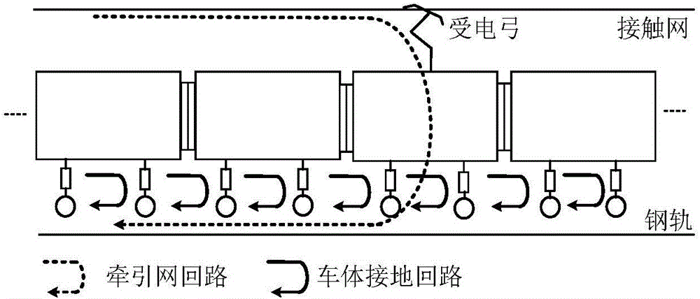
[0052] The traction network of the EMU under the direct power supply mode is selected as an example to verify the method of the present invention. The structure of the traction network corresponding to the direct power supply mode is composed of catenary and rails. The schematic diagram of the spatial distribution of the traction network is as follows Figure 4 As shown, the schematic diagram of the vehicle-network circuit is shown in Figure 5 shown. Figure 5Among them, the circuit 1 is the circuit formed by the catenary and the rail, and the circuit 2 is the circuit formed by the car body and the rail, which is referred to as the car body grounding circuit here. The current flowing through loop 1 is i 1 , the current flowing through loop 2 is i 2 , the current in the rail is i 0 .

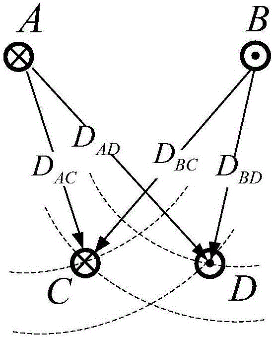
[0053] Depend on Image 6 It can be seen that in loop 1, the catenary current and rail current are in the same direction as the interlinked magnetic flux of loop 2, and then according to fo...

example 2

[0057] The traction network of the EMU under the direct belt return power supply mode is selected as an example to verify the method of the present invention. The direct supply belt return flow line power supply mode is improved on the basis of the direct power supply mode, and the overhead return line is connected in parallel on the rail, including ground line, the schematic diagram of its spatial distribution is shown in Figure 7 As shown, the schematic diagram of the vehicle-network circuit is shown in Figure 8 shown. according to Figure 8 , under this power supply mode, the traction network constitutes three loops, and there is electrical coupling between them and the ground loop of the car body.

[0058] Depend on Figure 8 It can be seen that the catenary-rail circuit ( Figure 5 Middle circuit 1) and vehicle body grounding circuit ( Figure 5 The mutual inductance between the middle circuit 2) has been obtained in the direct power supply mode. according to Fi...

example 3

[0067] The traction network of the EMU under the AT power supply mode is selected as a calculation example to verify the method of the present invention, and the spatial distribution diagram of the AT power supply mode traction network is as follows Figure 10 As shown, the schematic diagram of the vehicle network circuit corresponding to the AT power supply mode is as follows Figure 11 As shown, the magnetic field distribution of the ground loop of the car body under the AT power supply mode is as follows Figure 12 shown.

[0068] In this power supply mode, the traction network constitutes four loops, which are electrically coupled with the vehicle body ground loop respectively. Figure 5 Among them, catenary-rail circuit, catenary-ground wire circuit and car body ground circuit constitute circuit 1, circuit 5 and circuit 2 respectively. Mutual inductance M of catenary-rail loop, catenary-ground loop and car body ground loop obtained in the previous two power supply metho...


PUM


Abstract

The invention discloses a motor train unit ground loop electrical coupling effect coefficient calculating method. The motor train unit ground loop electrical coupling effect coefficient calculating method comprises the main steps of, firstly, according to traction network structures corresponding to different power supply manners, determining a train ground loop and the loops structured by different traction networks; secondly, calculating the magnetic chain of every traction network hoop, which is generated by current in a transmission conductor A and a return conductor B and is in mutual inductance with CD intersecting chains of the train ground loop; thirdly, calculating the electrical coupling coefficient of every traction network loop to the train group loop; lastly, superposing the calculating results to obtain the electric coupling effect coefficient of the entire traction network loop to the motor train unit ground loop. The motor train unit ground loop electrical coupling effect coefficient calculating method enhances the accuracy of train-network coupled modeling and is significant to train voltage fluctuation research, train ground circulation mechanism analysis and ground system optimization.

Description

technical field [0001] The invention relates to the field of analysis of safe operation of electrified railway EMUs, in particular to a calculation method for electrical coupling coefficients in grounding loops of EMUs. Background technique [0002] With the vigorous development of electrified railways, the safe and stable operation of EMUs has increasingly become the focus of attention. Working conditions such as the lifting bow of the EMU, pantograph-catenary offline, and lightning strikes will cause fluctuations in the voltage of the car body and uneven distribution of the potential of each car body. The car body is not only the reference ground potential of the on-board electrical and electronic equipment, but also the leakage channel for the protective grounding. The fluctuation of the car body voltage is likely to cause interference to the weak current equipment on the car. At the same time, although the grounding methods of EMUs of different models are quite differen...

Claims


Application Information

Patent Timeline
IPC IPC(8): B60M5/00
CPCB60M5/00
Inventor 刘志刚成业宋小翠黄可
Owner SOUTHWEST JIAOTONG UNIV
Why Eureka
Try Eureka