Automatic control system of vehicle lamps facing tunnel

An automatic control system and tunnel technology, applied in the direction of headlights, vehicle components, optical signals, etc., can solve the problems of unable to automatically control the status of lights and increase energy consumption, and achieve flexible and intelligent operation, energy saving and high efficiency The effect of automatic control

Inactive Publication Date: 2017-03-29
JIANGSU JINMI INTELLIGENT TECH CO LTD
View PDF7 Cites 3 Cited by
  • Summary
  • Abstract
  • Description
  • Claims
  • Application Information

AI Technical Summary

Problems solved by technology

[0008] The technical problem to be solved by the present invention is to overcome the deficiencies of the prior art, provide a tunnel-oriented vehicle lighting automatic control system, solve the problem that the existing vehicle lighting system cannot automatically control the status of the vehicle lights according to the driving situation of the vehicle, especially When entering the tunnel, because the lights in the tunnel are sufficient, but the vehicle is still in the lighting state after entering, the problem of increased energy consumption

Method used


Image

  • Automatic control system of vehicle lamps facing tunnel

Examples


Embodiment Construction

[0021] Embodiments of the present invention will be described below with reference to the accompanying drawings.

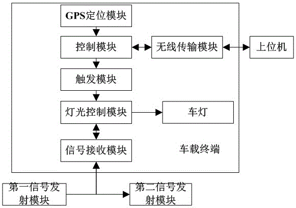
[0022] like figure 1 As shown, the present invention designs a tunnel-oriented vehicle lighting automatic control system, which specifically includes:

[0023] The host computer is used to store the position coordinate range of the road section where the tunnel is located, and compare the current position coordinates of the vehicle reported from the wireless transmission module with the position coordinate range of the road section where the tunnel is located, and feed back the comparison result to the wireless transmission module.

[0024] The tunnel terminal includes first and second signal transmission modules, the first signal transmission module is used to transmit signals to vehicles entering the tunnel; the second signal transmission module is used to transmit signals to vehicles that are about to leave the tunnel .

[0025] The vehicle-mounted terminal i...


PUM


Abstract

The invention discloses an automatic control system of vehicle lamps facing a tunnel. The automatic control system comprises an upper computer, a tunnel terminal and a vehicle-mounted terminal, wherein the upper computer is used for storing the position coordinate range of a road section where the tunnel is positioned, comparing the current vehicle position coordinate reported by a wireless transmission module with the position coordinate range, and feeding a result back to the wireless transmission module; the tunnel terminal comprises a first signal transmitting module and a second signal transmitting module; the vehicle-mounted terminal comprises a GPS locating module, a control module, the wireless transmission module, a trigger module, a light control module and a signal receiving module; the control module is further used for generating a second control signal according to the comparison result, and transmitting the second control signal to the light control module through the trigger module to enable the light control module to enter a working state; when the signal receiving module receives a transmitting signal of the first signal transmitting module, the light control module controls the vehicle lamps to be turned off; and when the signal receiving module receives a transmitting signal of the second signal transmitting module, the light control module controls the vehicle lamps to be turned on. According to the automatic control system, the vehicles entering the tunnel can be controlled in real time, turning on and turning off of the vehicle lamps are automatically achieved, and the energy consumption is reduced.

Description

technical field [0001] The invention relates to a tunnel-oriented vehicle lighting automatic control system, which belongs to the technical field of vehicle lighting control. Background technique [0002] With the continuous development of science and technology and the continuous progress of society, people are more and more inseparable from cars. Cars are not only a means of transportation, but also a symbol of social living standards and status. However, with the continuous increase of the number of cars, the car brings us a lot of traffic accidents while bringing us convenience. Therefore, driving safety has attracted more and more attention. [0003] The automotive lighting system is one of the three major safety parts of the car, and it is the most important active safety device, and it is becoming more and more intelligent. The automotive lighting control system is the intelligent control center of the automotive lighting system and an important part of the body ele...

Claims


Application Information

Patent Timeline
Patent Type & Authority Applications(China)
IPC IPC(8): B60Q1/08
CPCB60Q1/085B60Q2300/337
Inventor 贡伟东胡红兰李文涛陆辰钊
Owner JIANGSU JINMI INTELLIGENT TECH CO LTD
Why Eureka
Try Eureka