Urban traffic facility

A technology for urban transportation and facilities, applied in the direction of railway car body parts, roads, stations, etc., can solve the problems of trouble and inconvenient use of transportation facilities.

Active Publication Date: 2017-03-29
宁波市鄞州乐可机电科技有限公司
View PDF3 Cites 15 Cited by
  • Summary
  • Abstract
  • Description
  • Claims
  • Application Information

AI Technical Summary

Problems solved by technology

But in the actual simulation test, the traffic facility of this invention scheme also has some deficiencies, as follows: the traffic facility of this invention scheme is not convenient enough to use, and in the process of use, the trolley will be carried from the deceleration path to the acceleration path, which is very troublesome , in view of this, it is necessary to provide a technical solution to solve this problem

Method used


Image

  • Urban traffic facility
  • Urban traffic facility
  • Urban traffic facility

Examples


Embodiment 1

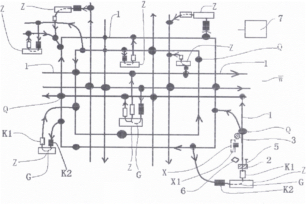
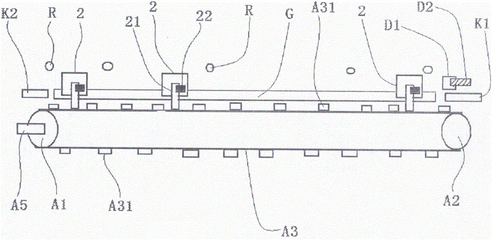
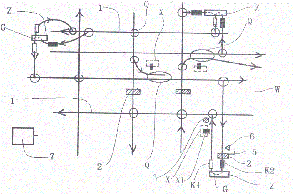
[0024] An urban transportation facility, comprising several platforms Z, several moving paths 1, several trolleys 2, several switching devices 3, several input devices 5, a starting position identification unit 6, and a control system 7; The carrier of directional movement, so that when the car 2 is combined on the movement path 1, the car 2 can move along the direction of the path; each movement path 1 is spliced ​​into a network traffic network W, and each platform Z is connected together through the traffic network W , each platform Z is connected to the head end of at least one moving path 1, and the moving path 1 whose head end is connected to platform Z is called an uplink path, and each platform Z is connected to the tail end of at least one moving path 1, and the tail end is connected to The movement path 1 connected to the station Z is called the downlink path. Among all the movement paths 1, the other movement paths except the uplink and downlink paths are called the ...

Embodiment 2

[0031] An urban transportation facility, comprising several platforms Z, several moving paths 1, several trolleys 2, several switching devices 3, several input devices 5, a starting position identification unit 6, and a control system 7; The carrier of directional movement, so that when the car 2 is combined on the movement path 1, the car 2 can move along the direction of the path; each movement path 1 is spliced ​​into a network traffic network W, and each platform Z is connected together through the traffic network W , each platform Z is connected to the head end of at least one moving path 1, and the moving path 1 whose head end is connected to platform Z is called an uplink path, and each platform Z is connected to the tail end of at least one moving path 1, and the tail end is connected to The movement path 1 connected to the station Z is called the downlink path. Among all the movement paths 1, the other movement paths except the uplink and downlink paths are called the ...

Embodiment 3

[0038] An urban transportation facility, comprising several platforms Z, several moving paths 1, several trolleys 2, several switching devices 3, several input devices 5, a starting position identification unit 6, and a control system 7; The carrier of directional movement, so that when the car 2 is combined on the movement path 1, the car 2 can move along the direction of the path; each movement path 1 is spliced ​​into a network traffic network W, and each platform Z is connected together through the traffic network W , each platform Z is connected to the head end of at least one moving path 1, and the moving path 1 whose head end is connected to platform Z is called an uplink path, and each platform Z is connected to the tail end of at least one moving path 1, and the tail end is connected to The movement path 1 connected to the station Z is called the downlink path. Among all the movement paths 1, the other movement paths except the uplink and downlink paths are called the ...


PUM


Abstract

The invention provides an urban traffic facility. The urban traffic facility comprises a plurality of platforms, a plurality of motion paths, a plurality of trolleys, a plurality of switching devices, a plurality of input devices, a start position identification unit and a control system. All the motion paths are connected to form a netted traffic network. All the platforms are connected together through the traffic network. The urban traffic facility further comprises a plurality of acceleration paths and a plurality of deceleration paths. The acceleration paths are used for accelerating the trolleys. The deceleration paths are used for decelerating the trolleys. One or more transition paths are arranged on each platform. The tail ends of the transition paths are connected with the deceleration paths so that the transition paths can receive the trolleys coming from the deceleration paths. The head ends of the transition paths are connected with the acceleration paths so that the trolleys on the transition paths can go into the acceleration paths. The urban traffic facility has the following advantages of being high in efficiency and convenient to use.

Description

technical field [0001] The solution of the invention relates to the construction field of urban traffic facilities. Background technique [0002] Modern transportation facilities use cars as carriers. After long-term development, this system has exposed insurmountable shortcomings, mainly as follows: 1. Inefficiency, sometimes a huge car can only carry a few people, and the car is at the platform and intersection. Also need to stop, two, easy to block, this point of the public has a deep understanding, will not go into details here, three, serious environmental pollution, mainly caused by automobile exhaust, in view of this, it is necessary to provide a kind of traffic facility, make it can overcome the above-mentioned shortcoming . The Chinese patent with the application number 201610289874.2 has made beneficial improvements, disclosing a traffic facility, including several platforms, several movement paths, several trolleys, several switching devices, several input device...

Claims


Application Information

Patent Timeline
Patent Type & Authority Applications(China)
IPC IPC(8): B61B1/00
CPCB61B1/00
Inventor 叶大可
Owner 宁波市鄞州乐可机电科技有限公司
Why Eureka
Try Eureka