Eureka AIR delivers breakthrough ideas for toughest innovation challenges, trusted by R&D personnel around the world.

Direct acting solenoid valve and four-way switching valve equipped with it as a pilot valve

A four-way switching valve, solenoid valve technology, applied in multi-way valves, valve devices, mechanical equipment and other directions, can solve problems such as noise, and achieve the effect of reducing noise

Active Publication Date: 2020-02-07
FUJIKOKI MFG CO LTD
View PDF7 Cites 0 Cited by
  • Summary
  • Abstract
  • Description
  • Claims
  • Application Information

AI Technical Summary

Problems solved by technology

Then, at the time of switching, the opening areas of the two ports change rapidly, and the high-pressure refrigerant suddenly flows into the low-pressure side port (pipe), and a sudden pressure change occurs in the system 200, causing a loud noise ( switch sound) problem

Method used


Image

  • Direct acting solenoid valve and four-way switching valve equipped with it as a pilot valve
  • Direct acting solenoid valve and four-way switching valve equipped with it as a pilot valve
  • Direct acting solenoid valve and four-way switching valve equipped with it as a pilot valve

Examples


no. 1 approach

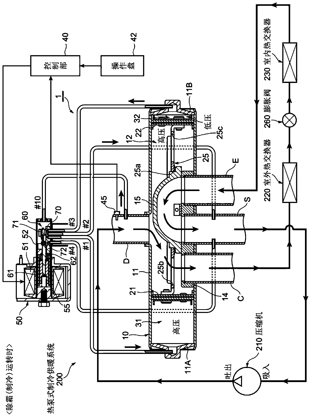
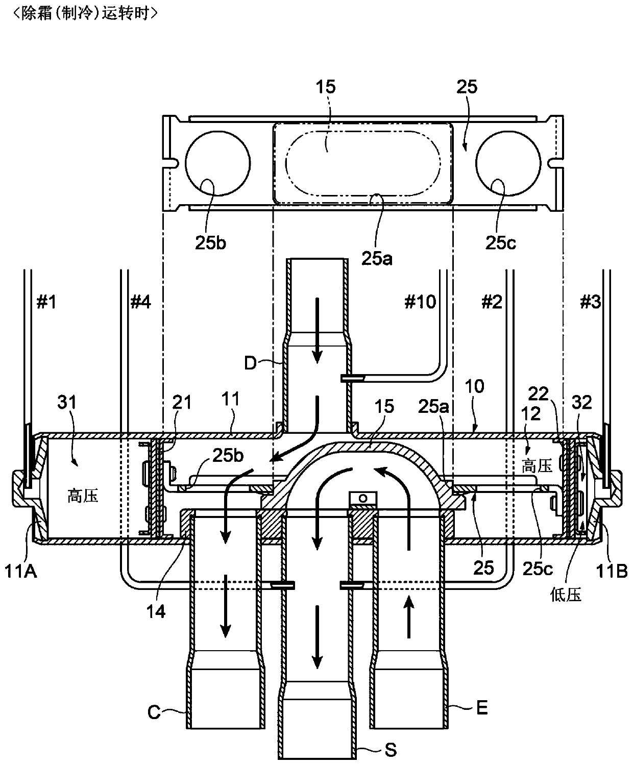
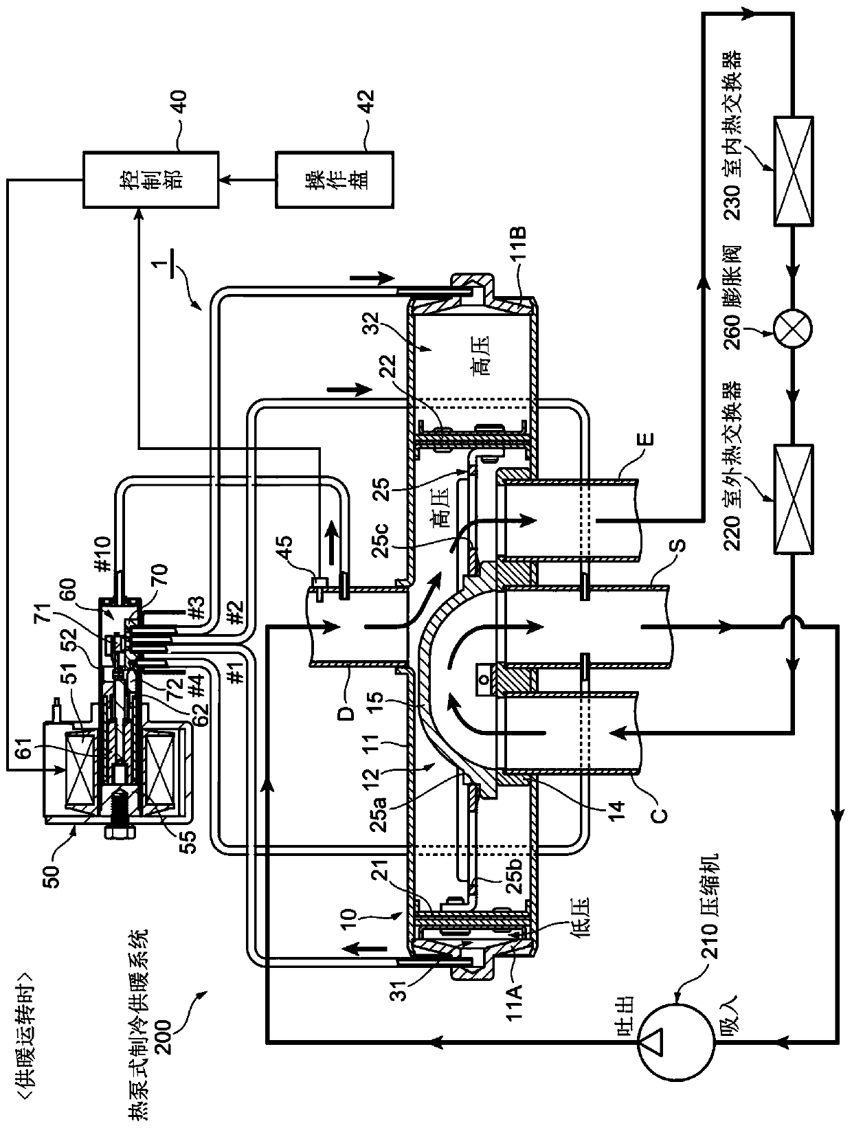
[0059] figure 1 It is an overall configuration diagram showing the cooling operation (defrosting operation) of a heat pump cooling and heating system incorporating the first embodiment of the direct-acting solenoid valve of the present invention as a pilot valve. Sliding four-way switching valve, figure 2 is to indicate figure 1 A sectional view with a partial plan view of the four-way valve body of the four-way switching valve shown during cooling operation (during defrosting operation), image 3 It is an overall configuration diagram showing the heating operation of a heat pump cooling and heating system, which is assembled with figure 1 Sliding four-way switching valve shown, Figure 4 is to indicate figure 1 An enlarged cross-sectional view with a partial plan view of the direct-acting solenoid valve of the first embodiment as a pilot valve of the shown four-way switching valve during a cooling operation (during a defrosting operation).

[0060] In addition, in t...

no. 2 approach

[0141] Figure 12A It is a side view showing a rotary four-way switching valve equipped with a second embodiment of the direct-acting solenoid valve of the present invention as a pilot valve, Figure 12B It is an upper surface side arrangement diagram of a cooling position and an upper surface side arrangement diagram of a heating position showing a rotary four-way switching valve including the second embodiment of the direct-acting solenoid valve of the present invention as a pilot valve. Figure 13 It is an overall configuration diagram showing the cooling operation (defrosting operation) of a heat pump cooling and heating system incorporating a Figure 12A , Figure 12B The rotary four-way switching valve shown (representing the Figure 12B X-X section of the cooling position). Figure 14 It is an overall configuration diagram showing the heating operation of a heat pump cooling and heating system, which is assembled with Figure 12A , Figure 12B The rotary four-way s...


PUM


Abstract

While being able to reduce noise effectively, without requiring lowering frequency of a compressor greatly from heating operation at the time of a change to defrosting operation. According to the voltage appied by the electromagnetic coil of the direct-acting electromagnetic valve, the first piston and the second piston are located at the absorption position and the non-abosrption position, the first valve core is located at one end position communicated with the end and the other end position communicated with the port, the second valve core is located at the opening position of the opening port and the closing position of the closing port. When the defrosting turning to the warming turning and warming turning to the defrosting turning are performed, the second valve core is located at the opening position, and the pressure of the main valve chamber reduces the presetting voltage.

Description

technical field [0001] The present invention relates to a guide-type four-way switching valve used for switching flow paths in a heat pump refrigeration and heating system, etc., and in particular, to a direct-acting solenoid valve capable of effectively reducing noise generated during operation switching before and after defrosting operation. , and a four-way switching valve provided as a pilot valve. Background technique [0002] In general, heat pump cooling and heating systems such as room air conditioners and automobile air conditioners include, in addition to a compressor, an outdoor heat exchanger, an indoor heat exchanger, and an expansion valve, etc., four flow path (flow direction) switching components. switch valve. [0003] refer to Figure 23A , Figure 23B An example of a heat pump cooling and heating system provided with such a four-way switching valve will be briefly described. The heat pump cooling and heating system 200 illustrated in the figure is confi...

Claims


Application Information

Patent Timeline
Patent Type & Authority Patents(China)
IPC IPC(8): F16K11/00F25B47/02
CPCF16K11/00F25B47/025
Inventor 小岛正至木船仁志森田纪幸
Owner FUJIKOKI MFG CO LTD
Why Eureka
Eureka Blog
Learn More