Optical frequency comb multi-section light wave splicing method of linear frequency sweeping light source with ultra-wide spectrum range

A swept frequency light source and optical frequency comb technology, applied in nonlinear optics, optics, instruments, etc., can solve the problem of difficult to achieve ultra-wide spectral range linear swept frequency light source, limit the number of linear swept frequency light waves, and the number of optical switch array switches. Less problems, to achieve the effect of realizing spectral range, avoiding laser relaxation oscillation, and realizing linear frequency sweep

Inactive Publication Date: 2017-03-29
TIANJIN UNIV
View PDF1 Cites 21 Cited by
  • Summary
  • Abstract
  • Description
  • Claims
  • Application Information

AI Technical Summary

Problems solved by technology

Therefore, this scheme can greatly improve the signal-to-noise ratio of the system; however, this scheme is still limited by the large AWG loss and the small number of switches in the optical switch array, which limits the number of linear frequency-sweeping light waves that can be seamlessly spliced, making it difficult to achieve Ultra-wide spectral range linear sweep source

Method used


Image

  • Optical frequency comb multi-section light wave splicing method of linear frequency sweeping light source with ultra-wide spectrum range
  • Optical frequency comb multi-section light wave splicing method of linear frequency sweeping light source with ultra-wide spectrum range
  • Optical frequency comb multi-section light wave splicing method of linear frequency sweeping light source with ultra-wide spectrum range

Examples


Embodiment Construction

[0037] Specific embodiments of the present invention will be described in detail below in conjunction with the accompanying drawings.

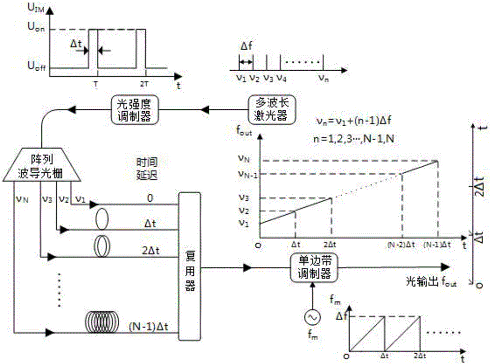
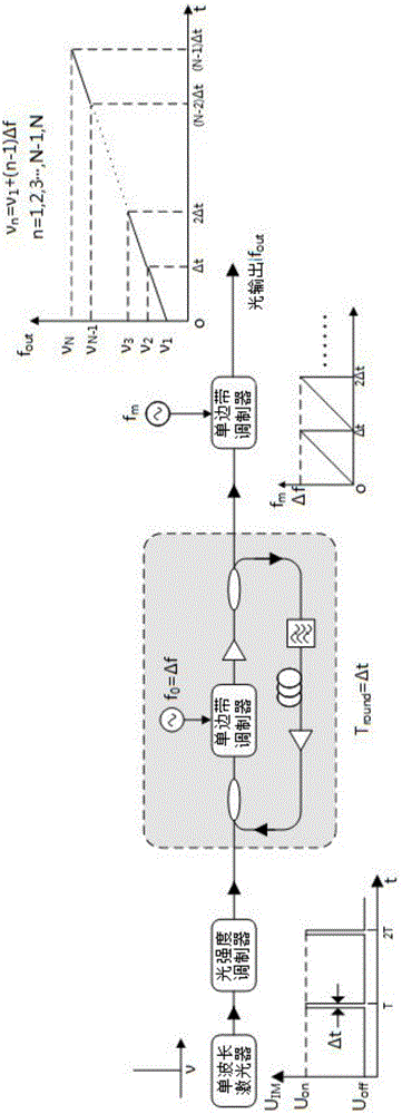
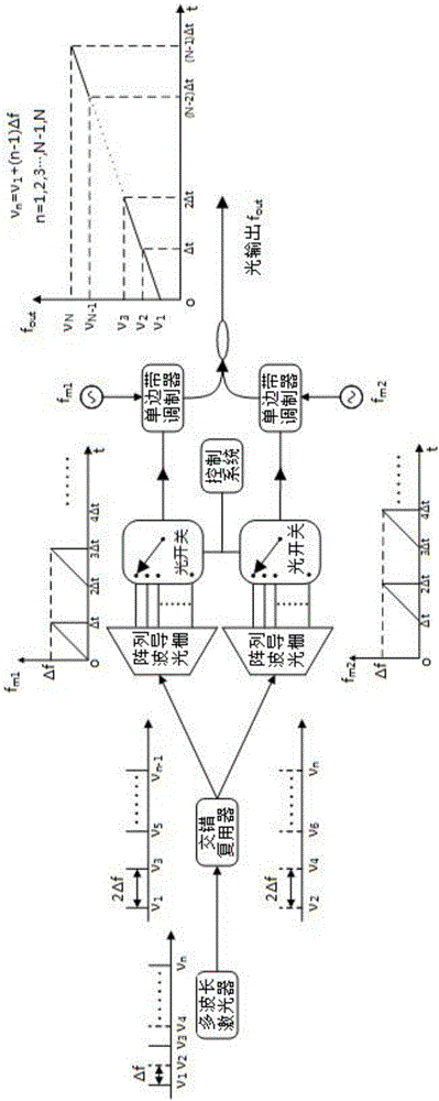
[0038] The optical frequency comb multi-segment light wave splicing method of the ultra-wide spectral range linear sweep frequency light source of the present invention adopts the precise optical frequency shifting technology, and the minimum optical frequency shifting interval can reach or be less than 0.1pm, so that the resolution ability of the spectrometer is no longer simply limited The dispersion ability of the light dispersion element (grating or prism) and the resolution ability (pixel unit size) of the CCD receiver are limited, so that the spectral resolution ability can be increased by two orders of magnitude, or higher.

[0039] Such as Figure 4 As shown, the technical solution of the present invention specifically includes the following steps:

[0040] Step 1. Realize multi-wavelength linear frequency sweep by using SSB optical m...


PUM


Abstract

The invention discloses an optical frequency comb multi-section light wave splicing method of a linear frequency sweeping light source with an ultra-wide spectrum range. The optical frequency comb multi-section light wave splicing method comprises the following steps: step 1, realizing multi-wavelength linear frequency sweeping through utilizing linear changes of light frequency along with time of multi-wavelength optical frequency comb light wave output from a single-sideband light modulator, so as to generate continuous light containing a multi-wavelength simultaneous linear frequency sweeping signal; step 2, adjusting a filter bandwidth of a continuous light signal through an electric control tunable filter, so as to enable a central frequency change speed to be the same as a frequency sweeping speed of frequency sweeping light wave; linearly changing the speed of a linear frequency sweeping speed gamma along with time until the central frequency reaches v1+(N-1)delta f and a central frequency initial value is equal to minimum frequency sweeping light frequency, so as to obtain linear frequency sweeping light wave with the ultra-wide spectrum range. Compared with the prior art, influences of laser relaxation vibration can be basically avoided, and the linear frequency sweeping speed with the extra-high speed can be realized; the frequency sweeping light source with high frequency sweeping linearity and high frequency precision is guaranteed.

Description

technical field [0001] The invention relates to the technical fields of laser radar, optical coherence tomography and spectral analysis, in particular to an optical frequency comb multi-segment light wave splicing scheme of an ultra-wide spectral range linear frequency sweep light source. Background technique [0002] In the laser radar (LiDAR) system, optical coherence tomography (OCT) imaging system and the new ultra-high resolution optical spectrum analyzer (OSA), a special light source or laser system is required, and the output frequency of the light source is required to change with A continuous light wave with constant intensity that changes linearly in time, and the wider the frequency range, the better, while maintaining extremely high linearity and frequency accuracy. [0003] In the LiDAR system, the pulse light source was first used. Due to the need to improve the distance resolution, people must continuously reduce the pulse width, which eventually leads to the ...

Claims


Application Information

Patent Timeline
Patent Type & Authority Applications(China)
IPC IPC(8): G02F1/01
CPCG02F1/0121
Inventor 葛春风杨天新郭成
Owner TIANJIN UNIV
Why Eureka
Try Eureka