
Semiconductor device

A semiconductor and substrate technology, applied in semiconductor/solid-state device manufacturing, electrical components, circuits, etc., can solve the problem of reducing the reliability of source electrodes and bus electrodes, and achieve the effect of inhibiting corrosion and improving reliability.

Active Publication Date: 2017-03-29
SANKEN ELECTRIC CO LTD
View PDF6 Cites 0 Cited by
  • Summary
  • Abstract
  • Description
  • Claims
  • Application Information

AI Technical Summary

Problems solved by technology

When moisture invades the upper surface of the silicon glass (BPSG) film from the outside of the semiconductor device, the phosphorus contained in the silicon glass (BPSG) film is released, corroding the nearby source electrode and the electrode of the bus line mainly made of Al surface, there is a problem that the reliability of electrodes such as source electrodes and bus lines is reduced

Method used


Image

  • Semiconductor device
  • Semiconductor device
  • Semiconductor device

Examples


Embodiment Construction

[0016] Next, a semiconductor device 1 as an embodiment of the present invention will be described.

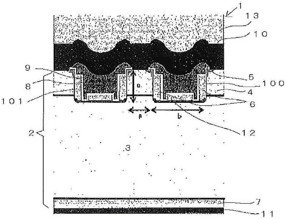
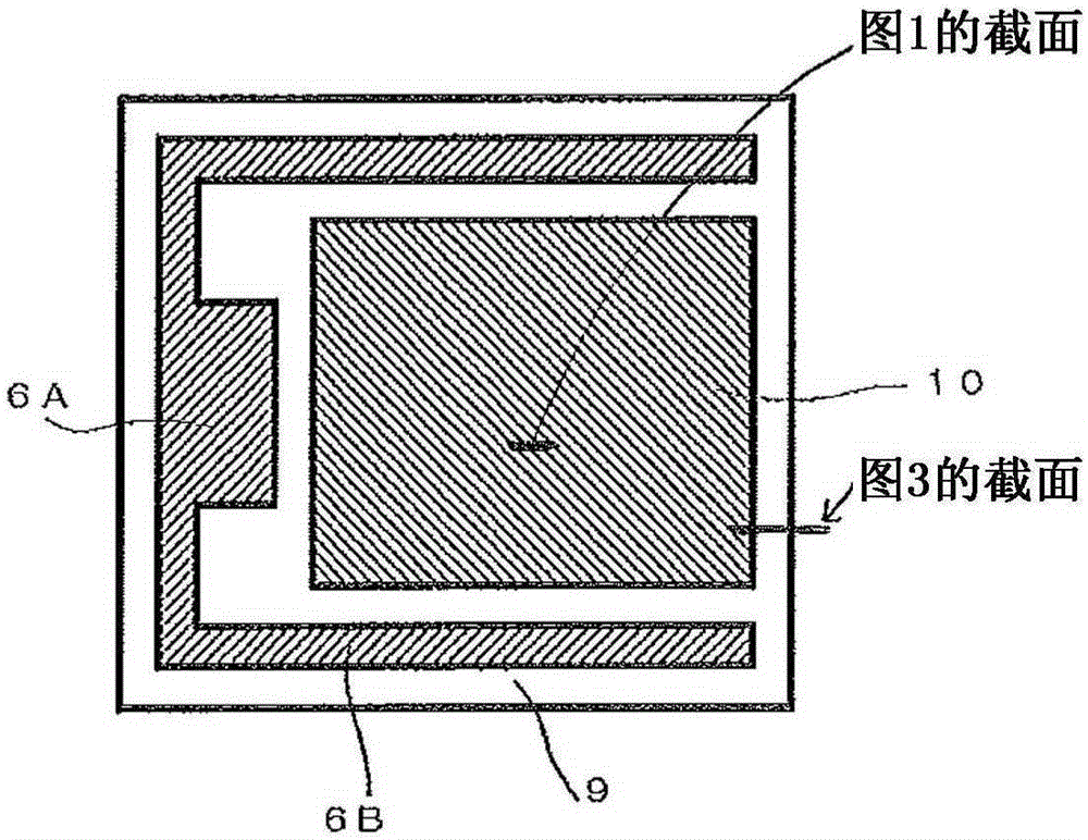
[0017] figure 1 A cross-sectional view of the semiconductor device 1 is shown. This semiconductor device 1 includes a trench gate type element portion (active region) formed on a semiconductor base 2 made of silicon. In this semiconductor substrate 2, an n-layer (first semiconductor region) 3 serving as a drift region and a p- layer (second semiconductor region) 4 serving as a base region are sequentially formed on a p-layer 7 serving as a collector region. A groove (gate trench) 100 penetrating through p − layer 4 and reaching n − layer 3 at the bottom is formed on the surface side of semiconductor substrate 2 . Slot 100 in with figure 1 Extended in the vertical direction of the paper, although not in the figure 2 It is shown in the plan view of , but a plurality of parallel grooves 100 are formed in the longitudinal direction of the paper. Here, the width b of the trenc...


PUM


Abstract

In one embodiment, a semiconductor device may include a controller that may be configured to receive an information signal from a detachable device wherein the information signal may be selectively representative of an output signal of the controller according to codes of the detachable device and to receive a sense input that may be representative of the output signal and to determine a code received from the detachable device according to a value of the sense signal and the information signal.

Description

technical field [0001] The present invention relates to semiconductor devices. Background technique [0002] In a structure in which a known switching element is formed on a semiconductor substrate, an interlayer film of undoped silica glass (NSG) is commonly used between the semiconductor substrate and electrodes above the semiconductor substrate. [0003] In such a structure, if there are steps on the semiconductor base, steps are likely to be formed in the interlayer film above it, and the electrodes may be disconnected above the region where the steps in the interlayer film are formed. Especially in the case where the upper surface of the semiconductor substrate is formed with grooves such as a known trench gate structure or a contact hole for source contact, relatively large steps are likely to be generated on the upper surface of the interlayer film. Therefore, there may be a problem that the source electrode and the bus line formed on the upper surface of the interla...

Claims


Application Information

Patent Timeline
Patent Type & Authority Applications(China)
IPC IPC(8): H01L21/02H01L21/316
CPCH01L21/02112H01L21/02123H01L21/022H01L21/02518H01L21/02521
Inventor 松田成修
Owner SANKEN ELECTRIC CO LTD
Learn More