
Novel method for reducing cogging torque of permanent magnet synchronous motor

A permanent magnet synchronous motor, cogging torque technology, applied in the direction of magnetic circuit rotating parts, magnetic circuit, electrical components, etc., can solve the problem of no calculation method and achieve the effect of reducing the simulation time

Active Publication Date: 2017-03-29
湖州菱创科技有限公司
View PDF2 Cites 22 Cited by
  • Summary
  • Abstract
  • Description
  • Claims
  • Application Information

AI Technical Summary

Problems solved by technology

The shape change of the permanent magnet is usually to change its pole arc coefficient or eccentricity. There are many researches on these two methods. Although the method of chamfering the permanent magnet angle used in this paper has been obtained by parametric experiments, the cogging rotation The law of change between moment and chamfering parameters, but no specific calculation method is given

Method used

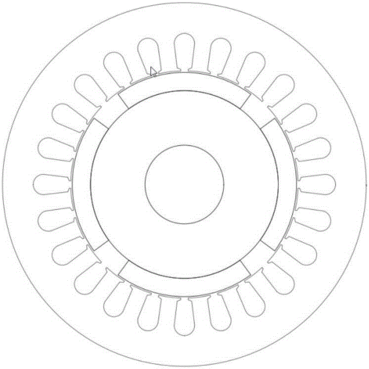

Image

  • Novel method for reducing cogging torque of permanent magnet synchronous motor
  • Novel method for reducing cogging torque of permanent magnet synchronous motor
  • Novel method for reducing cogging torque of permanent magnet synchronous motor

Examples


Embodiment Construction

[0032] The present invention will be further described below in conjunction with the accompanying drawings and specific embodiments.

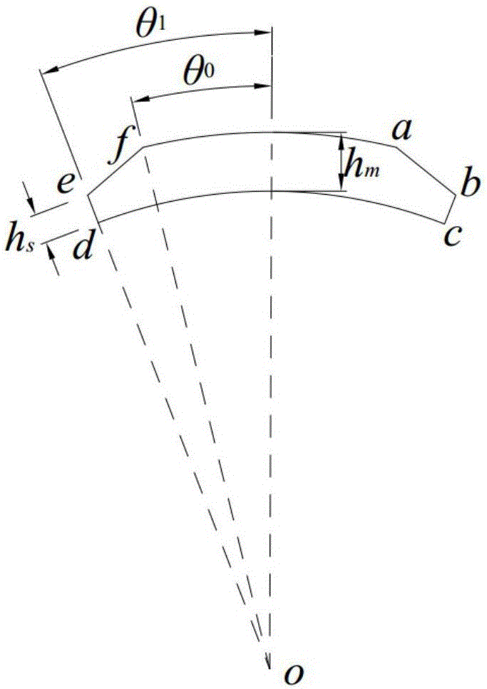
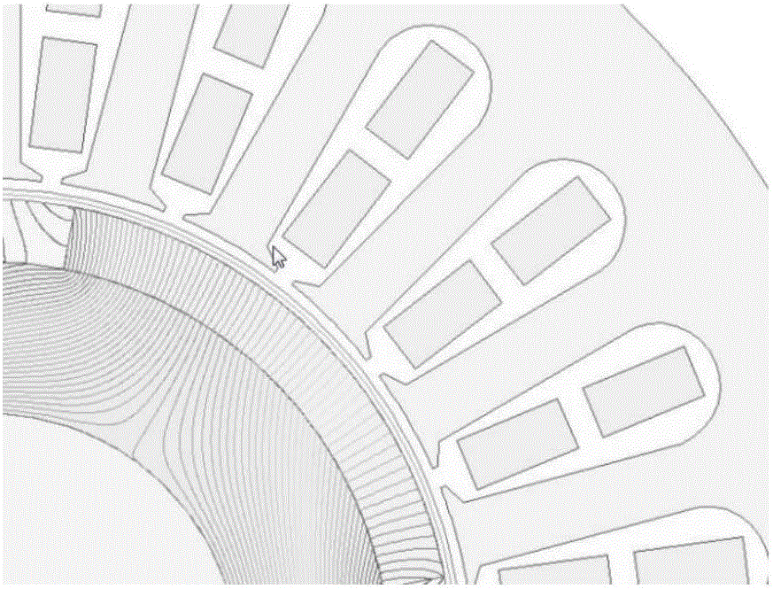
[0033] Permanent magnet structure of the present invention such as figure 2 as shown, image 3 It is a schematic diagram of magnetization of the permanent magnet of the present invention.

[0034] Such as figure 2 , The chamfering of the permanent magnet adopts a symmetrical way to the central axis. o is the center of arc af and arc cd, the lengths of ed and bc are equal, defined as h s , the permanent magnet thickness is defined as h m . h for h s and permanent magnet thickness h m The ratio of h s / h m , defined as the chamfer length proportional coefficient. θ 1 is the angle corresponding to the polar arc coefficient of the permanent magnet, that is, α p π / 2p, 0 is the angle of chamfering. If the angle of the chamfered corner is θ 0 Determined, then the determination method of h is as follows:

[0035]

[0036] in:

[0...


PUM


Abstract

The invention belongs to the technical field of surface-mounted permanent magnet synchronous motors, and provides an improved permanent magnet angle cutting method for the problem of reducing cogging torque. A cogging torque expression is deduced on the basis of an energy method and Fourier decomposition and a factor relationship of affecting the cogging torque is confirmed; and a fourier coefficient of residual magnetism square of a permanent magnet after angle cutting is deduced on the basis of radial magnetization of the permanent magnet, an optimal determining method of an angle cutting length proportion coefficient is provided, and the problem of minimization of the cogging torque is converted into solving of a minimum value of a secondary function. According to the method, the simulation time of the motor can be shortened while the calculation accuracy is ensured and the cogging torque of the motor is reduced.

Description

technical field [0001] This paper proposes a new weakening method for the cogging torque in the torque ripple component. Specifically, it refers to a method for reducing the cogging torque of the motor by changing the structural parameters of the permanent magnet of the surface-mounted permanent magnet synchronous motor, which belongs to the field of permanent magnet synchronous motor body design research. Background technique [0002] As an inherent phenomenon of the permanent magnet synchronous motor, the magnetic field of the permanent magnet interacts with the stator cogging to generate cogging torque, which in turn generates vibration and noise, which affects the control of the motor. In some systems that require high control accuracy, such as high-precision position and adaptive systems, cogging torque is one of the most important issues to consider. There have been many studies on weakening the cogging torque at home and abroad, for example, from the perspective of c...

Claims


Application Information

Patent Timeline
Patent Type & Authority Applications(China)
IPC IPC(8): H02K1/27
CPCH02K1/272H02K1/278
Inventor 白瑞林杨晓东
Owner 湖州菱创科技有限公司
Learn More