
Physical downlink control channel transmission method and device

A technology of physical downlink control and transmission method, which is applied to the separation device of transmission path, transmission system, digital transmission system, etc., and can solve the problems of increasing user equipment and increasing the complexity of base station implementation, etc.

Active Publication Date: 2017-03-29
HUAWEI TECH CO LTD
View PDF7 Cites 22 Cited by
  • Summary
  • Abstract
  • Description
  • Claims
  • Application Information

AI Technical Summary

Problems solved by technology

The number of antennas in the Massive MIMO antenna array can reach hundreds, which can lead to greater antenna gain, but at the same time form narrower antenna beams to ensure cell coverage
Currently in the LTE system, the Physical Control Format Indicator Channel (PCFICH, Physical Control Format Indicator Chanel) and PDCCH are sent on the full bandwidth of the entire system. If Massive MIMO technology is used to send PCFICH and PDCCH on the full bandwidth of the system with narrow beams, different beams transmit The overlapping of PCFICH and PDCCH data will increase the detection complexity of user equipment (UE, User Equipment), and will also increase the complexity of base station implementation
At present, there is no technology that can solve the problem of PCFICH and PDCCH transmission in multi-beam scenarios

Method used


Image

  • Physical downlink control channel transmission method and device
  • Physical downlink control channel transmission method and device
  • Physical downlink control channel transmission method and device

Examples


Embodiment Construction

[0080] The following will clearly and completely describe the technical solutions in the embodiments of the present invention with reference to the accompanying drawings in the embodiments of the present invention. Obviously, the described embodiments are only some, not all, embodiments of the present invention. Based on the embodiments of the present invention, all other embodiments obtained by persons of ordinary skill in the art without creative efforts fall within the protection scope of the present invention.

[0081] As used in this application, the terms "component," "module," "system" and the like are intended to refer to a computer-related entity, which may be hardware, firmware, a combination of hardware and software, software, or an operating system. software. For example, a component may be, but is not limited to being, a process running on a processor, a processor, an object, an executable, a thread of execution, a program, and / or a computer. As an example, both ...


PUM


Abstract

The present invention discloses a physical downlink control channel transmission method. The physical downlink control channel transmission method is used for a wireless network device to transmit N signal sets, wherein each signal set is used for transmitting the control information of one or more second wireless network devices, the signals of the signal sets include PDCCHs (physical downlink control channel), or PDCCHs and PCFICHs (physical control format indication channel). The method includes the step that the first wireless network device sends signal sets to the second wireless network devices on resources which can be occupied by each signal set, wherein the first wireless network device carries out sending processing on each signal set, wherein the sending processing comprises at one kind of processing selected from multiplexing, scrambling, modulation, interleaving and resource mapping. With the physical downlink control channel transmission method provided by the technical schemes of the invention adopted, interference between the signal sets can be eliminated, the transmission reliability of the PCFICHs and the PDCCHs can be improved, and therefore, the second wireless network devices can receive the PCFICHs and the PDCCHs on the resources of received signal sets, and the signal detection complexity of the second wireless network devices can be decreased.

Description

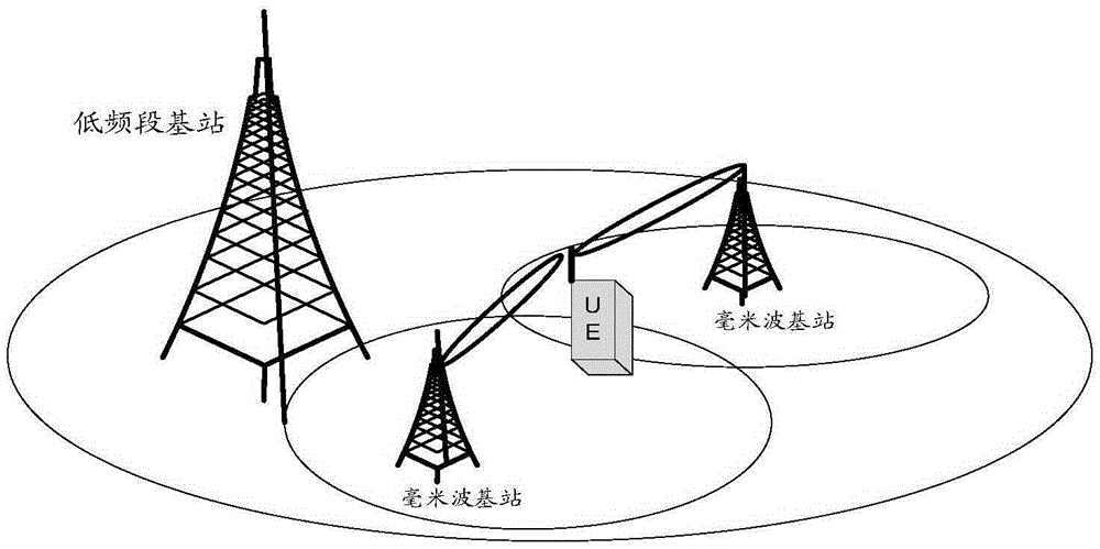
technical field [0001] The present invention relates to the field of communication technology, in particular to a transmission method, device and system of a physical downlink control channel. Background technique [0002] In the Long Term Evolution (LTE, Long Term Evolution) system, the Physical Downlink Control Channel (PDCCH, Physical Downlink Control Channel) is used to transmit downlink control information (DCI, Downlink Control Information) to the user equipment (UE, UserEquipment), such as uplink scheduling Instructions, downlink data transmission instructions, and public control information, etc., DCI includes control information such as resource allocation, transmission format, power control, frequency hopping type, and transmission mode. [0003] A centimeter wave (centimeter wave) frequency band generally refers to a frequency spectrum ranging from 3 GHz to 30 GHz, and a millimeter wave frequency band generally refers to a frequency spectrum ranging from 3 GHz to ...

Claims


Application Information

Patent Timeline
IPC IPC(8): H04L5/00H04W72/04
CPCH04L5/0053H04W72/23H04L5/003H04L5/0005H04W72/0446
Inventor 王婷李元杰
Owner HUAWEI TECH CO LTD
Learn More