A data transmission method and data processing device

A data transmission method and equipment technology, applied in the electronic field, can solve the problems of receiving errors, reduced communication efficiency, and sampling misalignment at the receiving end.

Active Publication Date: 2019-08-27
TENDYRON CORP
View PDF5 Cites 0 Cited by
  • Summary
  • Abstract
  • Description
  • Claims
  • Application Information

AI Technical Summary

Problems solved by technology

When the frequency difference between the sending clock and the receiving clock is too large, it will cause sampling misalignment at the receiving end, resulting in receiving errors and lower communication efficiency.

Method used


Image

  • A data transmission method and data processing device
  • A data transmission method and data processing device
  • A data transmission method and data processing device

Examples


Embodiment 1

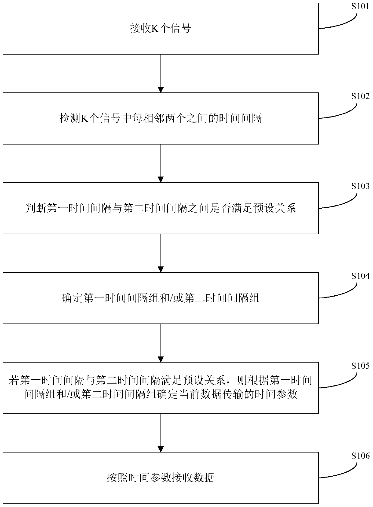
[0065] Such as figure 1 As shown, this embodiment provides a data transmission method. In order to achieve the above purpose, the technical solution of the present invention is specifically implemented as follows:

[0066] Step S101: receiving K signals;

[0067] K is a preset value, K≥3 and K is an odd number. For example, if K=5 is preset, then when 5 signals are received in total, the 5 signals received are processed. The method provided in this embodiment It can be judged by the relationship between the time intervals between the K signals whether to start receiving data, that is, if the preset relationship is satisfied and the data is started to be received after K signals, the K signals can be regarded as indicating the start of data reception. Handshake signal; where the signal can be a pulse signal, that is, a high-level pulse signal (rising edge signal) or a low-level pulse signal (falling edge signal) is received, and the pulse signal can be a square wave, a sine wa...

Embodiment 2

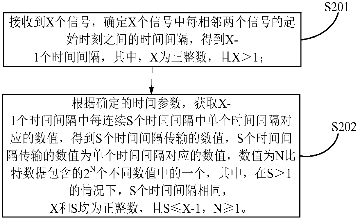
[0138] This embodiment provides a data receiving method, figure 2 is based on this Example 1 figure 1 An optional flow chart of receiving data according to the time parameters determined by the handshake signal for the shown data transmission.

[0139] Such as figure 2 As shown, receiving data according to the time parameter determined by the handshake signal includes the following steps:

[0140] In step S201, X signals are received, and the time interval between the starting moments of every two adjacent signals among the X signals is determined to obtain X-1 time intervals, where X is a positive integer and X>1.

[0141] In an optional implementation manner of this embodiment, receiving X signals may be detecting X low-level pulses, or detecting X high-level pulses. The low-level pulse / high-level pulse can be represented by a square wave, sine wave, triangular wave, etc., which can distinguish high-level pulses from low-level pulses, and there is no limitation here. I...

Embodiment 3

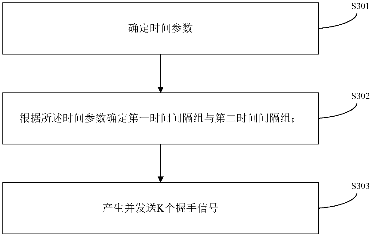
[0188] Such as image 3 As shown, this embodiment provides a data transmission method. In order to achieve the above purpose, the technical solution of the present invention is specifically implemented as follows:

[0189] Step S301: Determine the time parameter;

[0190]As an optional implementation in this embodiment, the time parameter may include a first time parameter and / or a second time parameter. For the convenience of description, in this embodiment, the first time parameter is recorded as etu, and the second time parameter is The parameter is denoted as pdt, the first time parameter etu and the second time parameter pdt all represent a period of time value, such as etu=0.1 second, pdt=0.01 second, this value is negotiated and determined by the data sending end and the receiving end, utilize this time parameter to be able to To determine the time interval for sending the handshake signal, the receiving end can determine it according to the received handshake signal. ...


PUM


Abstract

The present application provides a data transmission method and data processing device. The method comprises: receiving K signals; detecting a time interval between every two adjacent signals in the K signals; determining whether a first time interval and a second time interval meet a preset relationship; determining a first time interval group and / or a second time interval group; if the first time interval and the second time interval meet the preset relationship, determining a time parameter of current data transmission according to the first time interval group and / or the second time interval group; and receiving data according to the time parameter. The present application can ensure the stability and accuracy of each data transmission, and effectively avoids the technical problems of receiving error and reduced communication efficiency caused by sampling misalignment of a receive end when the difference between a transmit clock and a receiving time parameter is too large.

Description

technical field [0001] The invention relates to the field of electronic technology, in particular to a data transmission method and data processing equipment. Background technique [0002] The serial communication methods between electronic circuits are mainly divided into synchronous communication methods and asynchronous communication methods. The synchronous communication method requires the two parties to communicate at the same clock frequency and to coordinate accurately. By sharing a single clock or timing pulse source to ensure accurate synchronization between the sender and the receiver, the efficiency is high; the asynchronous communication method does not require both parties to be synchronized. Can use their own clock sources, the two parties follow an asynchronous communication protocol, and use characters as the data transmission unit. The time interval for the sender to transmit characters is uncertain, and the transmission efficiency is lower than that of syn...

Claims


Application Information

Patent Timeline
Patent Type & Authority Patents(China)
IPC IPC(8): H04L7/00
Inventor 李东声
Owner TENDYRON CORP
Why Eureka
Try Eureka