
Planing equipment for last blade windows of steam turbine rotor

A steam turbine rotor and window technology, applied in metal processing equipment, planer, planer/slotting machine, etc., can solve the problems of increasing the auxiliary preparation time and reducing the processing efficiency of the end leaf window, etc., to achieve the reduction of auxiliary preparation time, simple and light structure, The effect of improving processing efficiency

Inactive Publication Date: 2017-04-05
SHANGHAI ELECTRIC POWER GENERATION EQUIPMENT CO LTD
View PDF10 Cites 2 Cited by
  • Summary
  • Abstract
  • Description
  • Claims
  • Application Information

AI Technical Summary

Problems solved by technology

However, when the modified planer is used to plan the multi-level final leaf windows on the rotor, the following defects still exist: when processing different levels of final leaf windows, it is necessary to continuously move, repeatedly remove and repeatedly install the planer, and it is necessary to carry out multiple adjustments. Therefore, the auxiliary preparation time before planing is greatly increased, thereby reducing the processing efficiency of the last leaf window

Method used


Image

  • Planing equipment for last blade windows of steam turbine rotor
  • Planing equipment for last blade windows of steam turbine rotor
  • Planing equipment for last blade windows of steam turbine rotor

Examples


Embodiment Construction

[0067] The implementation of the present invention will be illustrated by specific specific examples below, and those skilled in the art can easily understand other advantages and effects of the present invention from the contents disclosed in this specification.

[0068]It should be noted that the structures, proportions, sizes, etc. shown in the drawings attached to this specification are only used to match the content disclosed in the specification, for those who are familiar with this technology to understand and read, and are not used to limit the implementation of the present invention. Limiting conditions, so there is no technical substantive meaning, any modification of structure, change of proportional relationship or adjustment of size, without affecting the effect and purpose of the present invention, should still fall within the scope of the present invention. The disclosed technical content must be within the scope covered. At the same time, terms such as "upper",...


PUM


Abstract

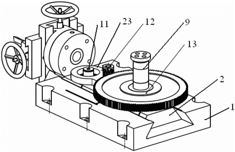
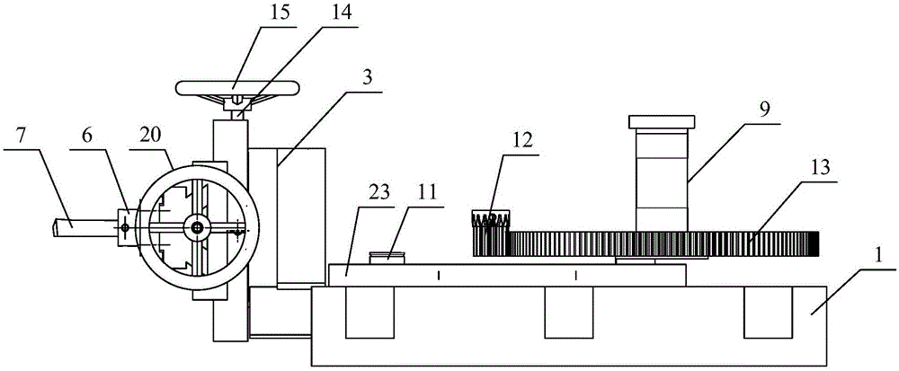
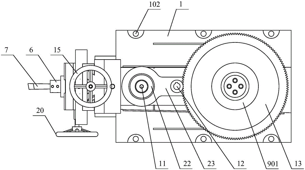
The invention provides planing equipment for last blade windows of a steam turbine rotor. The planing equipment comprises a base, a ram, a rotary table, a first layer board, a second layer board, a knife rest fixed on the second layer board and a planer tool fixed on the knife rest. The base is mounted on a worktable of an existing machine tool, an accommodating groove which penetrates through left and right and is matched with the ram is formed in the base, and the ram is accommodated in the accommodating groove and can perform a straight reciprocating motion along the left and right direction; the rotary table is fixedly connected to the ram, the first layer board is connected to the rotary table and can perform a linear motion along an up and down direction; the second layer is connected to the first layer board and can perform a linear motion along the front and back direction. The planing equipment is simple and light in structure, and can be mounted on the worktable of the existing machine tool. A to-be-machined rotor is fixed on the existing machine tool, so that axial fast movement can be realized by using the planing equipment to machine different stage last blade windows on a same rotor, and therefore, movement, mounting and tuning many times can be canceled, and the machining efficiency is greatly improved.

Description

technical field [0001] The invention relates to a steam turbine part processing device, in particular to a planing device for the last blade window of the steam turbine rotor. Background technique [0002] A steam turbine is a rotary power machine that converts steam energy into mechanical work, also known as a steam turbine, and is mainly used as a prime mover for power generation. The steam turbine includes a rotor and multi-stage blades arranged on the rotor, and each stage of blade includes a plurality of blades, and the rotor is provided with multi-stage wheel grooves (also called T-shaped grooves) for installing multi-stage blades. In addition, in order to facilitate the insertion of the blades into the T-shaped slots, each stage of the wheel groove is provided with a final leaf window, and each blade in the stage of blades is put into the stage of the wheel groove from the last leaf window. After the last leaf in the box is placed in the final leaf window position. ...

Claims


Application Information

Patent Timeline
Patent Type & Authority Applications(China)
IPC IPC(8): B23D1/08B23D7/06B23Q1/26B23Q5/34
Inventor 刘毅赵文兵刘路
Owner SHANGHAI ELECTRIC POWER GENERATION EQUIPMENT CO LTD
Learn More