
Bearing system on paper transferring roller of printing machine

A printing machine and rolling bearing technology, which is applied in the field of printing machine parts, can solve the problems of printing drawings and paper inclination, waste of paper, vibration and wear, etc., and achieve the effect of preventing radial runout, reducing damage probability, and good rotation flexibility

Inactive Publication Date: 2017-04-05
TIANJIN ZEYANG PRINTING
View PDF0 Cites 2 Cited by
  • Summary
  • Abstract
  • Description
  • Claims
  • Application Information

AI Technical Summary

Problems solved by technology

However, during the printing work, it was found that due to the radial runout of the transfer cylinder, the printed drawing and the paper would be inclined, which seriously affected the printing effect and printing quality, reduced the printing efficiency, and wasted a lot of paper
In addition, the bearings have a certain radial play in order to be able to simply slide the bearings onto the journal, which has a negative effect on the printing quality, because in the presence of radial play, the printing roller or the anilox Vibration and wear of rollers that can adversely affect print quality, with various quality problems in prints
In this case, the bearings running at high speed are prone to serious damage very quickly. Usually, a new bearing will be rusted and worn within a short time after it is replaced, and the situation continues to deteriorate, which increases the maintenance rate and the scrapping of printed materials rate, which not only affects normal production, but also brings great economic losses to printing manufacturers

Method used


Image

  • Bearing system on paper transferring roller of printing machine

Examples


Embodiment Construction

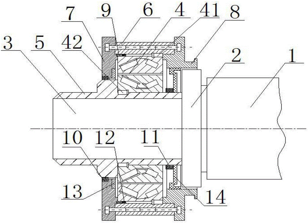
[0017] Such as figure 1 As shown, the present invention provides a bearing system on the transfer cylinder of a printing machine. A roller pillow 2 is provided on the end surface of the paper transfer cylinder 1, and a journal 3 is provided on the extension side of the roller pillow 2 . Its bearing system includes a rolling bearing 4, a shaft sleeve 5, an upper end cover 6, a left end cover 7 and a right end cover 8, wherein the shaft sleeve 5 is set on the journal 3, and the upper end cover 6, the left end cover 7 and the right end cover 8 are respectively located on the shaft The top, left and right sides of the cover 5, and the right end cover 8 is close to the rolling pillow 2. The shaft sleeve 5, the upper end cover 6, the left end cover 7 and the right end cover 8 form a sealed space, and the rolling bearing 4 is installed in the sealed space.

[0018] In addition, a dustproof ring 9 , a retaining ring and a sealing ring are installed in the sealed space, wherein the du...


PUM


Abstract

The invention provides a bearing system on a paper transferring roller of a printing machine. The bearing system comprises the paper transferring roller, a cylinder bearer arranged on the end face of the paper transferring roller, a journal arranged on the extension side of the cylinder bearer and a rolling bearing arranged on the journal in a sleeving mode, wherein the rolling bearing is installed in sealed space composed of a shaft sleeve, an upper end cover, a left end cover and a right end cover, and a dust ring, a check ring and a seal ring are installed in the sealed space. The rolling bearing comprises an inner rolling bearing ring and an outer rolling bearing ring, the outer rolling bearing ring is provided with first bolt holes, the rolling bearing is fixed to the upper end cover through the first bolt holes, and the inner rolling bearing ring is provided with second bolt holes and is fixed to the shaft sleeve through the second bolt holes. The bearing system has the beneficial effects that the structure is reasonable, the rotation accuracy is high, the radial clearance is small, and the usage rate of the bearing can be increased.

Description

technical field [0001] The invention relates to the technical field of printing machine parts, in particular to a bearing system on a paper delivery cylinder of a printing machine. Background technique [0002] The printing press cylinder is an important part of the printing press. In the paper transfer system of the printing press, the paper is transferred through the rotation of the transfer cylinder. The traditional paper transfer rollers are installed with transmission gears, cams and other parts through the shaft heads at both ends of the roller, and the bearings are connected to the journals provided between the roller and the shaft heads. Through the cooperation between the bearings and the journals, the rollers are guaranteed Run at a constant speed. However, during the printing work, it was found that due to the radial runout of the paper delivery cylinder, the printing drawing and the paper would be inclined, which seriously affected the printing effect and printi...

Claims


Application Information

Patent Timeline
IPC IPC(8): B41F13/193
Inventor 艾德宪艾阳
Owner TIANJIN ZEYANG PRINTING
Learn More