Time difference method ultrasonic flowmeter

An ultrasonic and flowmeter technology, applied in the direction of measuring flow/mass flow, liquid/fluid solid measurement, measuring devices, etc., can solve the problems of flowmeter performance degradation, flow fluctuation error, IC integration, etc., to improve energy utilization rate , increase the installation distance, improve the effect of measurement accuracy

Active Publication Date: 2017-04-05
美卓伦仪表中国有限公司
View PDF15 Cites 3 Cited by
  • Summary
  • Abstract
  • Description
  • Claims
  • Application Information

AI Technical Summary

Problems solved by technology

In the traditional ultrasonic flowmeter, the ultrasonic transducer is used as both an ultrasonic transmitter and an ultrasonic receiver, and is in a state of discontinuous sampling, and the data acquisition rate is low (see Chinese patent CN102261937A, a high-precision time difference ultrasonic flowmeter and its flow rate Measurement methods)
Moreover, during the sampling process, since the downstream sampling and countercurrent sampling are not at the same time, large errors will occur due to flow fluc

Method used


Image

  • Time difference method ultrasonic flowmeter
  • Time difference method ultrasonic flowmeter
  • Time difference method ultrasonic flowmeter

Examples


Embodiment Construction

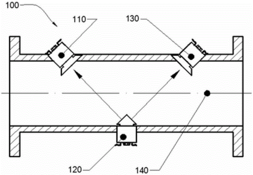
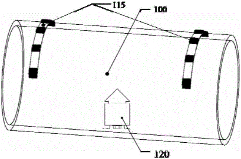
[0022] see Figure 1~6 The transit-time ultrasonic flowmeter 100 according to the embodiment of the present invention includes an ultrasonic transducer 120 with a tapered matching layer, a reverse flow ultrasonic receiver 110 , a downstream ultrasonic receiver 130 , and a pipe 140 . The ultrasonic transducer 120 with a tapered matching layer is only used as an ultrasonic transmitter and continuously emits ultrasonic waves during operation, while the ultrasonic receiver 110 and downstream ultrasonic receiver 130 are only used as ultrasonic receivers, so the ultrasonic flowmeter 100 transmits and receives ultrasonic waves. Ultrasonic can be carried out simultaneously, compared with the traditional time-sharing ultrasonic flowmeter, it reduces the error caused by different measurement time when the flow fluctuates, and increases the data collection rate.

[0023] Since the piezoelectric ultrasonic transducer has a higher output sound pressure than the capacitive ultrasonic transd...


PUM


Abstract

The invention provides a time difference method ultrasonic flowmeter, and relates to an ultrasonic flowmeter. According to the time difference method ultrasonic flowmeter, the data acquisition rate of the ultrasonic flowmeter is improved; the data acquisition synchronization is improved; the measurement accuracy is improved; the time difference method ultrasonic flowmeter is provided with an ultrasonic transducer, ultrasonic receivers and a pipe; the ultrasonic transducer is used as an ultrasonic emitter; the ultrasonic receivers are arranged on both sides of the ultrasonic transducers; the ultrasonic transducer is provided with a tapered matching layer, an insulating adhesive, a piezoelectric sheet, a tail mass block, a prestressed screw and a wire; and the piezoelectric sheet, the tapered matching layer and the tail mass block are connected through the prestressed screw. By changing the installation mode of the ultrasonic flowmeter, the ultrasonic transducer with the tapered matching layer is used as the ultrasonic emitter. Downstream sampling and countercurrent sampling are synchronized. The measurement accuracy is improved. The sampling rate of the ultrasonic flowmeter can be improved.

Description

technical field [0001] The invention relates to an ultrasonic flowmeter, in particular to a time-difference method ultrasonic flowmeter. Background technique [0002] Ultrasonic flowmeter, as a non-contact flow measuring instrument without moving parts, has gradually replaced traditional mechanical flowmeters due to its advantages of high precision, large range, wide bandwidth, high stability, and no influence on the fluid state during the measurement process. type flow meter. In the ultrasonic flowmeter based on the time difference method, in the traditional Z-type measurement, when the fluid flows at the speed u, the actual propagation speed c of the ultrasonic wave is the sound speed c 0 With the superposition of the fluid in the ultrasonic velocity component ucosθ, there will be a time difference between the forward flow and the reverse flow of the ultrasonic wave, so that the flow rate can be detected according to the relationship between the time difference and the fl...

Claims


Application Information

Patent Timeline
IPC IPC(8): G01F1/66
CPCG01F1/662
Inventor 王凌云李威李岸林孙道恒
Owner 美卓伦仪表中国有限公司
Why Eureka
Try Eureka