
A kind of preparation method of led fluorescent glass lens

A fluorescent glass and lens technology, applied in glass manufacturing equipment, glass molding, manufacturing tools, etc., to achieve the effects of low energy consumption, reduced processing procedures, and short time

Active Publication Date: 2019-07-26
RESEARCH INSTITUTE OF TSINGHUA UNIVERSITY IN SHENZHEN
View PDF6 Cites 0 Cited by
  • Summary
  • Abstract
  • Description
  • Claims
  • Application Information

AI Technical Summary

Problems solved by technology

[0007] The purpose of the present invention is to solve the problem that the fluorescent glass body obtained by sintering needs to be used for LED packaging through secondary processing in the prior art, and proposes a method for preparing LED fluorescent glass lenses, which can be used for one-time sintering and molding. Fluorescent Glass Lens for White LED Packaging

Method used


Image

  • A kind of preparation method of led fluorescent glass lens
  • A kind of preparation method of led fluorescent glass lens
  • A kind of preparation method of led fluorescent glass lens

Examples


Embodiment 1

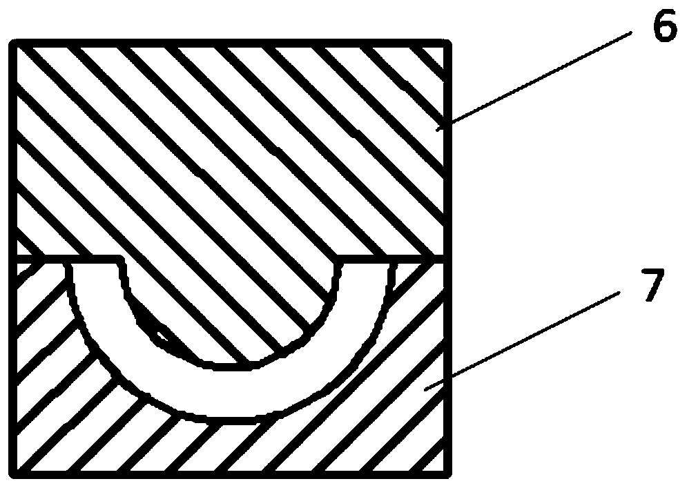
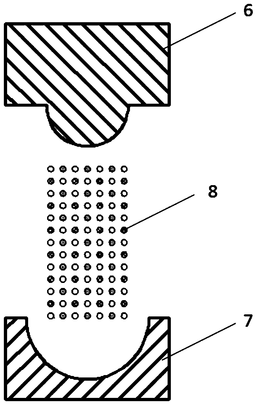
[0031] Embodiment 1 of the present invention uses a discharge plasma sintering machine to provide a method for preparing a fluorescent glass lens for a white light LED. The equipment required by the method includes: a plasma discharge sintering machine, a precision numerical control machine tool, and a planetary ball mill. The required raw materials include: graphite, which is used as the indenter for processing the sintering chamber; silicon oxide, aluminum oxide and yttrium oxide, which are used as the main substrates of the fluorescent glass body; and cerium oxide, which is used as the phosphor in the fluorescent glass body. The preparation method of fluorescent glass lens for LED of this embodiment comprises the following steps:

[0032] S1: According to the shape and size of the lens required by the LED module, process the upper and lower graphite indenters in the target chamber of the discharge plasma sintering machine to make it a mold for sintering fluorescent glass le...

Embodiment 2

[0042] In the preparation method of the LED fluorescent glass lens of this embodiment, in step S2, the raw material powder of the fluorescent glass lens has a specific proportion (in molar percentage): 65% of aluminum oxide, 12% of silicon oxide, 19% of yttrium oxide, Cerium is 4%. The operations of other steps are the same as those in Embodiment 1, and will not be repeated here.

Embodiment 3

[0044] In the preparation method of the LED fluorescent glass lens of this embodiment, in step S2, the raw material powder of the fluorescent glass lens has a specific proportion (in molar percentage): 60% of aluminum oxide, 14.75% of silicon oxide, 25% of yttrium oxide, Cerium is 0.25%. The operations of other steps are the same as those in Embodiment 1, and will not be repeated here.


PUM


Abstract

The invention belongs to the field of light emitting materials and in particular relates to a preparation method of an LED (Light Emitting Diode) fluorescent glass lens. The preparation method comprises the following steps: S1: machining upper and lower graphite pressing heads in a target chamber of a discharge plasma sintering machine according to the shape and size of a lens needed by an LED module, so as to form a mold for sintering the fluorescent glass lens; S2: grinding raw materials of the fluorescent glass lens into powder and uniformly mixing; S3: charging the fluorescent glass powder, which is uniformly mixed, into the machined pressing head mold and compacting; finishing sintering in the discharge plasma sintering machine. By adopting the preparation method of the LED fluorescent glass lens, provided by the invention, a remote laser fluorescent glass lens for packaging a white-light LED can be formed by one-step sintering, so that machining procedures are reduced and the working efficiency is improved. Compared with other sintering technologies, a discharge plasma sintering technology needs lower temperature and lower energy consumption when being used for forming same glass bodies, and the energy utilization rate is higher and the time is shorter.

Description

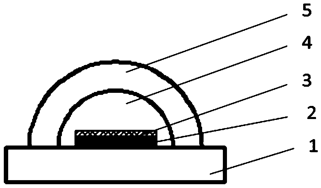
technical field [0001] The invention belongs to the field of luminescent materials, and in particular relates to a method for preparing a fluorescent glass lens for a white light LED. Background technique [0002] In the prior art, blue LED chips combined with yellow phosphor powder are the most common white LED products, and have become the mainstream of white LEDs. However, the phosphor powder directly coated on the surface of the LED chip is susceptible to aging and light decay due to the influence of temperature, and is not easy to disperse evenly and cause color spots, and the consistency is difficult to meet the application requirements of high color rendering and backlight. Take the classic white LED imitation lumen package as an example, such as figure 1 Shown: the LED chip is bonded on the heat sink or the substrate 1 through solder bonding, and then soldered gold wires to complete the electrical connection, and then the chip 2 is coated with silica gel 3 mixed wit...

Claims


Application Information

Patent Timeline
Patent Type & Authority Patents(China)
IPC IPC(8): C03B19/06C03C3/062
CPCC03B19/063C03C3/062
Inventor 周霖胡益民曹鸣皋敬刚刘岩
Owner RESEARCH INSTITUTE OF TSINGHUA UNIVERSITY IN SHENZHEN
Learn More