Variable air pressure braking energy recovery device and method
An energy recovery device and pneumatic braking technology, which is applied in the direction of electromechanical devices, mechanical energy control, electric components, etc., can solve the existing problems of energy loss, resource waste, energy loss, etc., to improve energy utilization and reduce vehicle costs , the effect of reducing energy consumption
- Summary
- Abstract
- Description
- Claims
- Application Information
AI Technical Summary
Problems solved by technology
Method used
Image
Examples
Embodiment 1
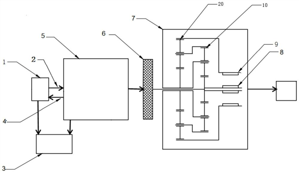
[0024] This embodiment provides a variable air pressure braking energy recovery device, refer to figure 1 As shown, it includes a brake air pump 1, an air storage tank 5, a controller 3, a turbine 6, a double-rotor counter-rotating motor 7, a pressure sensor arranged in the air storage tank 5, an exhaust valve arranged in the brake air pump 1 and The first exhaust pipe 2 between the air storage tanks 5, and the second return pipe 4 arranged between the return valve of the brake air pump 1 and the air storage tank 5; the controller 3 is connected with the pressure sensor for Receive the pressure signal in the air storage tank 5 from the pressure sensor; The controller 3 is connected with the vehicle braking system for receiving the braking signal from the vehicle braking system; the exhaust valve and the return valve of the brake air pump 1, the storage The exhaust valves of the gas tank 5 are all controlled by the controller 3 .
[0025] The first exhaust pipe 2 is used for: ...
Embodiment 2
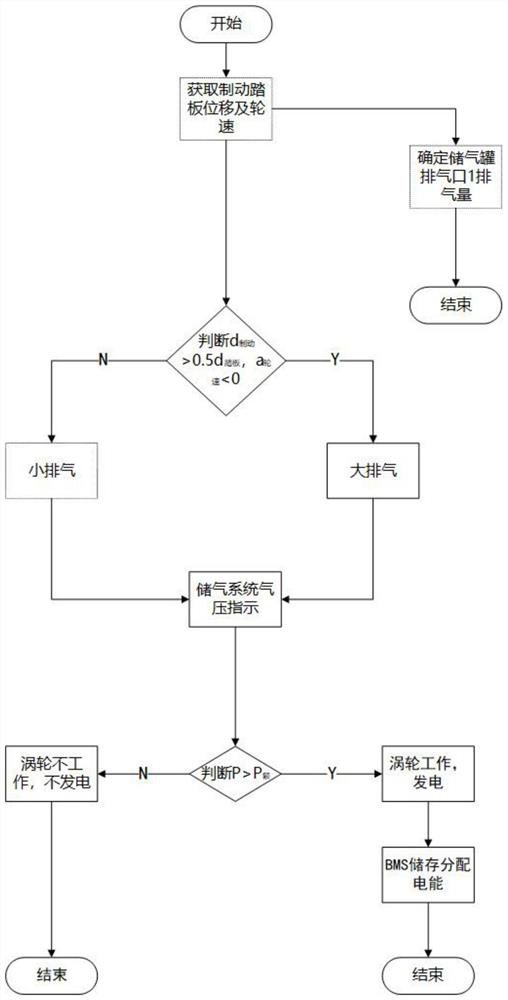
[0033] This embodiment provides a variable air pressure braking energy recovery method, which is applied to the variable air pressure braking energy recovery device described in Embodiment 1. Refer to image 3 shown, including the following steps:
[0034] Step 1, receiving the braking signal from the vehicle braking system, and judging the subdivision type corresponding to the braking signal;
[0035] Step 2, control the brake air pump 1 to discharge gas to the gas storage tank 5, and the gas discharge amount is determined according to the subdivision type of the brake signal;
[0036] Step 3, when the pressure in the air storage tank 5 reaches the brake pressure P 制 At this time, the air storage tank 5 is controlled to release air toward the turbine 6 to make the turbine 6 rotate and work, and the output shaft of the turbine 6 drives the dual-rotor counter-rotating motor 7 to work, converting mechanical energy into electrical energy for storage.
[0037] In a more optimal ...
PUM
 Abstract
Description
Claims
Application Information
 - R&D
- Intellectual Property
- Life Sciences
- Materials
- Tech Scout
- Unparalleled Data Quality
- Higher Quality Content
- 60% Fewer Hallucinations
Browse by: Latest US Patents, China's latest patents, Technical Efficacy Thesaurus, Application Domain, Technology Topic, Popular Technical Reports.
© 2025 PatSnap. All rights reserved.Legal|Privacy policy|Modern Slavery Act Transparency Statement|Sitemap|About US| Contact US: help@patsnap.com


