
Debugging method and debugging system for distribution automation equipment

A power distribution automation and debugging system technology, which is applied in the direction of circuit breaker testing, measuring electricity, measuring electrical variables, etc., can solve the problems of affecting the debugging effect, heavy workload, and difficulty in providing AC working power, so as to reduce the debugging workload , the effect of verifying the accuracy

Active Publication Date: 2017-04-05
XIANNING POWER SUPPLY COMPANY OF STATE GRID HUBEIELECTRIC POWER +2
View PDF8 Cites 17 Cited by
  • Summary
  • Abstract
  • Description
  • Claims
  • Application Information

AI Technical Summary

Problems solved by technology

[0004] (1) The workload of online debugging is too large, which affects the debugging effect
Due to the large number of equipment in the project and many manufacturers involved, the workload of new construction, replacement and transformation of primary and secondary equipment is often large, coupled with the requirements for power supply reliability, it is very difficult to implement online debugging and commissioning, and it is difficult to achieve the expected results
In addition, during the online debugging process, especially the FTU terminal debugging, it is difficult to provide AC working power on site, which brings difficulties to the normal development of the debugging work
[0005] (2) Quality control work is difficult to close the loop
Since the equipment is in live running state, it is very difficult to rectify the problem after the online debugging finds the problem

Method used


Image

  • Debugging method and debugging system for distribution automation equipment
  • Debugging method and debugging system for distribution automation equipment
  • Debugging method and debugging system for distribution automation equipment

Examples


Embodiment Construction

[0055] The technical solutions in the present invention will be clearly and completely described below in conjunction with specific embodiments.

[0056] The invention provides a debugging method for power distribution automation equipment. The power distribution automation equipment debugging method includes a single test method for power distribution automation terminals and switchgear, a transformer ratio test method, and a master station for power distribution automation equipment. System joint debugging method.

[0057] A method for debugging power distribution automation equipment, comprising the steps of:

[0058] Step 1. Single test of distribution automation terminal and switchgear:

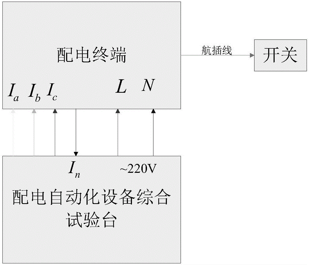
[0059] The schematic diagram of the single test system of distribution automation terminal and switchgear in one embodiment of the present invention is as follows figure 1 As shown, the described distribution automation terminal and switchgear unit test system is a subsystem of a distr...


PUM


Abstract

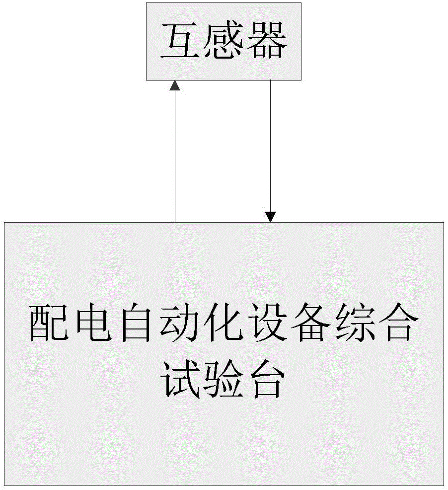
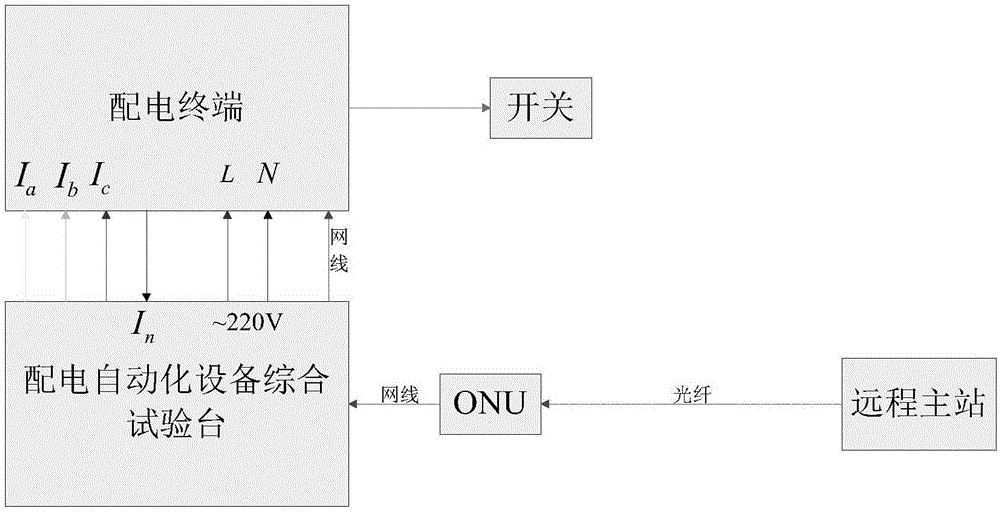
The invention relates to the technical field of distribution automation testing, particularly to a debugging method and debugging system for distribution automation equipment. The method comprises the following steps that: step one, distribution automation terminal and single switch device testing is carried out; to be specific, whether a distribution automation terminal and a single switch device meet standards is determined; step two, transformer transformation ratio testing is carried out; to be specific, transformers are connected with a power supply of a distribution automation equipment integrated test bench by power lines and are connected with a transformer transformation ratio tester by test lines; during single transformer testing, the current magnitude of the current transformer increases and the voltage of the voltage transformer increases, transformation ratios of the transformers are detected, correlated power data are calculated and corresponding recording is made, and whether the transformers meet standards is detected; and step three, joint debugging of a distribution automation equipment zone main station system is carried out; to be specific, whether joint debugging of an equipment zone main station system meets a standard is detected. Using the method and system, the field debugging workload can be reduced.

Description

technical field [0001] The invention relates to the technical field of distribution automation testing, in particular to a debugging method and a debugging system for distribution automation equipment. Background technique [0002] At present, the State Grid Corporation of China is vigorously promoting the construction of distribution automation, by installing automation terminals (for providing switch status information and control functions) and transformers (for switch analog measurement and terminal power supply) next to traditional distribution network switches. ), and establish a communication channel with the dispatching master station to realize the functions of remote monitoring of distribution network switches, distribution SCADA, feeder automation, topology analysis, ring disassembly, load transfer, fault detection and location by the control department, so as to further improve the distribution network power supply reliability. [0003] In order to reduce the pr...

Claims


Application Information

Patent Timeline
Patent Type & Authority Applications(China)
IPC IPC(8): G01R31/00G01R31/327G01R35/02
CPCG01R31/00G01R31/327G01R35/02
Inventor 金昭柯向阳张侃君黄光咸熊军雷伟韩振
Owner XIANNING POWER SUPPLY COMPANY OF STATE GRID HUBEIELECTRIC POWER
Learn More