
Method removing semiconductor substrate mask layer

A mask layer and semiconductor technology, applied in semiconductor/solid-state device manufacturing, electrical components, circuits, etc., can solve problems such as no longer usable, damaged LTO structure, scrapped wafers, etc.

Active Publication Date: 2017-04-05
CSMC TECH FAB2 CO LTD
View PDF3 Cites 5 Cited by
  • Summary
  • Abstract
  • Description
  • Claims
  • Application Information

AI Technical Summary

Problems solved by technology

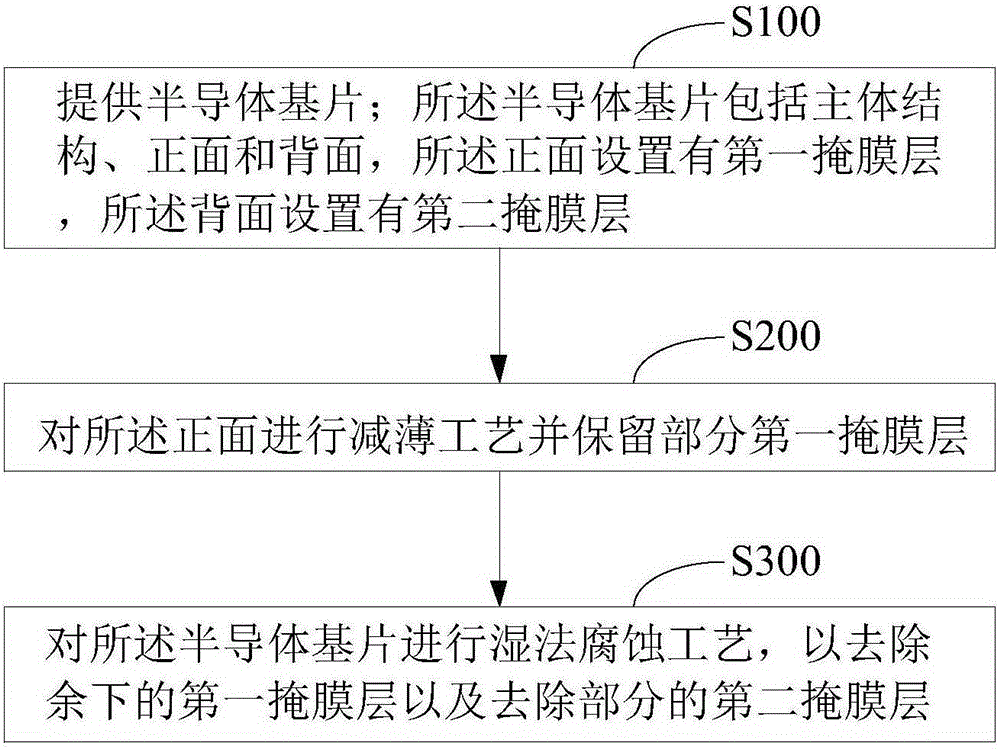
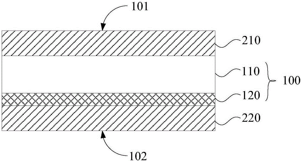
However, there is a layer of Low Temperature Oxide (LTO) on the back of the wafer used in DMOS products to form a back seal structure. After the silicon dioxide film layer exceeds the standard, when the front silicon dioxide film layer is reworked and removed, the acidic liquid usually corrodes to the LTO structure on the back of the wafer, thereby damaging the LTO structure and thus damaging the wafer, and may even cause the wafer to be directly scrapped and cannot be used again

Method used


Image

  • Method removing semiconductor substrate mask layer
  • Method removing semiconductor substrate mask layer
  • Method removing semiconductor substrate mask layer

Examples


Embodiment Construction

[0024] In order to facilitate the understanding of the present invention, the present invention will be described more fully below with reference to the associated drawings. Preferred embodiments of the invention are shown in the accompanying drawings. However, the present invention can be embodied in many different forms and is not limited to the embodiments described herein. On the contrary, these embodiments are provided to make the understanding of the disclosure of the present invention more thorough and comprehensive.

[0025] Unless otherwise defined, all technical and scientific terms used herein have the same meaning as commonly understood by one of ordinary skill in the technical field of the invention. The terms used herein in the description of the present invention are for the purpose of describing specific embodiments only, and are not intended to limit the present invention. As used herein, the term "and / or" includes any and all combinations of one or more of ...


PUM

PropertyMeasurementUnit
Thicknessaaaaaaaaaa
Thicknessaaaaaaaaaa
Thicknessaaaaaaaaaa

Abstract

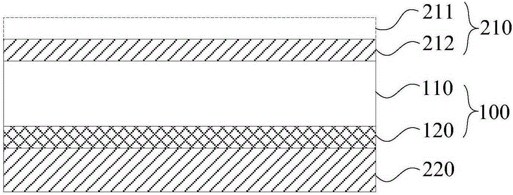
A method removing a semiconductor substrate mask layer comprises the following steps: thinning the front side of the substrate so as to remove partial the first mask layer; using wet method corrosion technology on the substrate so as to remove residual first mask layer and partial the second mask layer. An LTO structure close to the backside of the substrate is protected by the second mask layer, and cannot be damaged by the wet method corrosion technology, thus well protecting the LTO structure, preventing wafer damages, and reducing wafer discarding risks.

Description

technical field [0001] The invention relates to the technical field of semiconductor devices, in particular to a method for removing a mask layer of a semiconductor substrate. Background technique [0002] A trench double diffused field effect transistor (Double Diffused MOSFET, DMOS) product needs to form a trench (Trench) to make a gate structure. In order to obtain trenches, tetraethyl orthosilicate (TEOS) is usually decomposed into silicon dioxide to form a hard mask, and then the trench structure is obtained through an etching or etching process. The silicon dioxide film layer blocks the positions that do not need to be etched or etched, thereby obtaining the trench structure. [0003] The silicon dioxide film formed by TEOS decomposition is usually deposited through a low-pressure furnace tube, so that the silicon dioxide film is deposited on the front and back of the wafer. During the deposition process, abnormalities may occur, resulting in excessive particles in t...

Claims


Application Information

Patent Timeline
IPC IPC(8): H01L21/311H01L21/306
CPCH01L21/30625H01L21/31111
Inventor 平梁良但唐龙
Owner CSMC TECH FAB2 CO LTD
Learn More