Turret welding device for welding steel plates

A welding device and turret technology, applied in auxiliary devices, welding equipment, auxiliary welding equipment, etc., can solve the problems of waste of production personnel, increase production costs, difficult welding operations, etc., and achieve convenient welding, improve accuracy, and improve precision. Effect

Active Publication Date: 2017-04-19
华安钢宝利高新汽车板加工(常熟)有限公司
View PDF5 Cites 3 Cited by
  • Summary
  • Abstract
  • Description
  • Claims
  • Application Information

AI Technical Summary

Problems solved by technology

[0002] Welding is a manufacturing process and technology for joining metal or other thermoplastic materials by means of heating, high temperature or high pressure; the existing welding method is to bring two workpieces to be welded into contact with each other, and heat the flux at the contact point to make it Melt and cover the above welding parts. After the molten flux cools, the contact parts of the two workpieces to be welded are firmly connected together. During the actual welding operation, the welder often holds the steel plate to be welded in one hand and the welding machine in the other. Welding, this method not only has a slow welding speed, but also when the steel plate to be welded is large in size, it is difficult for the welder to support it with one hand, making it difficult to carry out the welding operation smoothly, and one person supports the other for welding, which will cause the production personnel to be injured. Waste, virtually increases the production cost

Method used


Image

  • Turret welding device for welding steel plates
  • Turret welding device for welding steel plates
  • Turret welding device for welding steel plates

Examples


Embodiment Construction

[0027] In order to enable those skilled in the art to better understand the technical solution of the present invention, the present invention will be described in detail below in conjunction with the accompanying drawings. The description in this part is only exemplary and explanatory, and should not have any limiting effect on the protection scope of the present invention. .

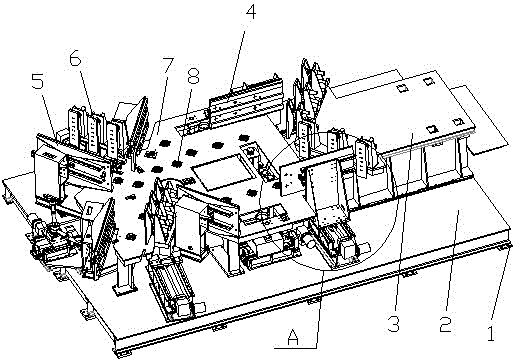
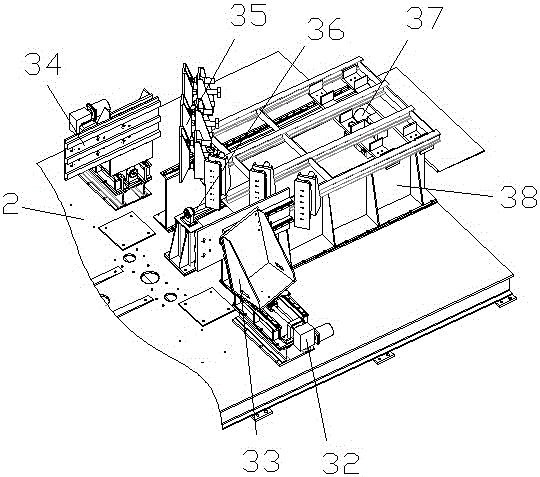
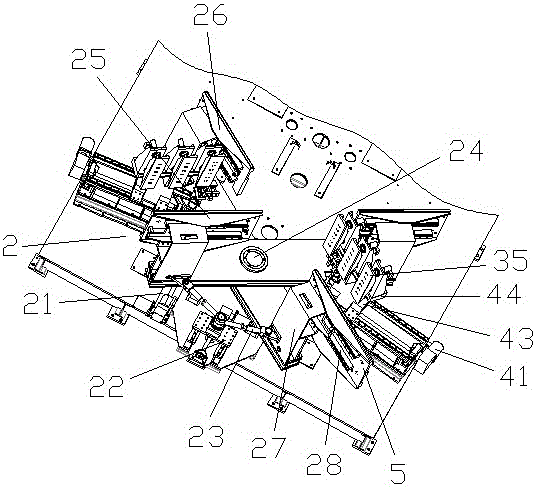
[0028] like Figure 1-Figure 4 As shown, the specific structure of the present invention is: a turret welding device for steel plate welding, which includes a bottom plate 2, the bottom of the bottom plate 2 is provided with a fixed leaf 1, the middle part is provided with a mounting plate 7, the left A turret mechanism is provided, a left and right moving mechanism 3 is provided on the right side, a first positioning device 4 is provided on the front and rear sides, a suction cup 8 is provided on the mounting plate 7, and a third positioning device is provided on the right side of the turret structure...


PUM


Abstract

The invention relates to a turret welding device for welding steel plates. The turret welding device for welding the steel plates comprises a base plate. Fixing blade plates are arranged on the lower side of the base plate. An installation plate is arranged in the middle of the base plate. A turret mechanism is arranged on the left portion. A left-right movement mechanism is arranged on the right portion of the base plate. First locating devices are arranged on the front and back sides of the base plate. Suction cups are arranged on the installation plate. A third locating device is arranged on the right side of the turret mechanism. A second locating device is arranged on the left side of the turret mechanism. The second locating device is matched with a clamping device arranged on the left portion of the installation plate. A clamping device matched with the first locating device is arranged at the left end of the left-right movement mechanism. The turret welding device for the welding steel plates aims to achieve the effects that the steel plates large in volume are fixed to the installation plate through the turret and the suction cups on the installation plate, the steel plates to be welded are located through the locating devices and clamped through the clamping devices, and then welding is conducted; and in this way, manpower is greatly saved, and the work effect is improved.

Description

technical field [0001] The invention relates to the field of welding equipment, in particular to a turret welding device used for welding steel plates. Background technique [0002] Welding is a manufacturing process and technology for joining metal or other thermoplastic materials by means of heating, high temperature or high pressure; the existing welding method is to bring two workpieces to be welded into contact with each other, and heat the flux at the contact point to make it Melt and cover the above welding parts. After the molten flux cools, the contact parts of the two workpieces to be welded are firmly connected together. During the actual welding operation, the welder often holds the steel plate to be welded in one hand and the welding machine in the other. Welding, this method not only has a slow welding speed, but also when the steel plate to be welded is large in size, it is difficult for the welder to support it with one hand, making it difficult to carry out ...

Claims


Application Information

Patent Timeline
Patent Type & Authority Applications(China)
IPC IPC(8): B23K37/04
CPCB23K37/04B23K37/0408B23K37/0443B23K2101/18
Inventor 不公告发明人
Owner 华安钢宝利高新汽车板加工(常熟)有限公司
Why Eureka
Try Eureka