Aircraft built-in engine installation structure and its moving assembly method

An installation structure and engine technology, applied in aircraft assembly, power plant arrangement/installation, aircraft parts, etc., can solve the problem that the convenience, safety, speed, and accuracy of aircraft built-in engine installation cannot meet the requirements of coordination, unity, and vertical integration. Problems such as complex conversion of hoisting product stations, etc., to achieve the effect of convenient operation and simple installation structure

Active Publication Date: 2019-01-11
THE GENERAL DESIGNING INST OF HUBEI SPACE TECH ACAD
View PDF5 Cites 1 Cited by
  • Summary
  • Abstract
  • Description
  • Claims
  • Application Information

AI Technical Summary

Problems solved by technology

Although this method can guarantee the shape and protective performance of the aircraft shell, its vertical hoisting involves complex conversion of product stations, and must rely on the guarantee of large facilities
It can be seen that the above two methods cannot meet the requirements of coordination and unity in terms of the convenience, safety, speed, and accuracy of the installation of aircraft built-in engines.

Method used


Image

  • Aircraft built-in engine installation structure and its moving assembly method
  • Aircraft built-in engine installation structure and its moving assembly method
  • Aircraft built-in engine installation structure and its moving assembly method

Examples


Embodiment Construction

[0030] The aircraft built-in engine installation structure and its step-by-step assembly method of the present invention will be further described in detail below in conjunction with the accompanying drawings and specific embodiments.

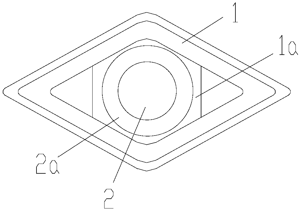
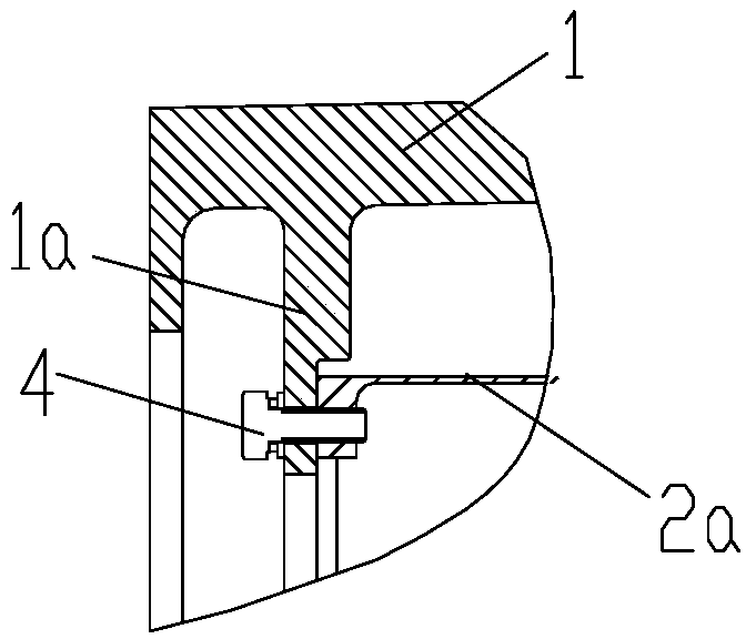
[0031] Such as Figure 1~5 As shown, the aircraft built-in engine mounting structure of the present invention includes a protective cover 1 as an aircraft load-bearing shell and an engine 2 fixedly installed in the inner cavity of the protective cover 1, and the protective cover 1 and the engine 2 are coaxially arranged. The front part of the protective cover 1 is integrally formed with an end face installation frame 1a, and the head of the engine 2 is provided with an end face connection frame 2a. Fitted and connected, so that the head of the engine 2 is axially fixed in the front cavity of the protective cover 1; the rear part of the protective cover 1 is integrally formed with the shaft section support frame 1b in an open structure, and the ...


PUM


Abstract

The invention discloses a mounting structure for an aircraft built-in type engine and a shifting assembly method for the mounting structure. The mounting structure comprises a protective cover and an engine which is fixedly mounted in an inner cavity of the protective cover; an end surface mounting frame is arranged on the front part of the protective cover; an end surface connecting frame is arranged on the head of the engine; the two end surface connecting frames are connected in a tightly-fit mode through a first bolt assembly, so that the head of the engine is fixedly arranged in a front inner cavity of the protective cover; and a shaft section supporting frame is arranged on the rear part of the protective cover, the tail part of the engine is seated on the shaft section supporting frame, and a fastening hoop is arranged above the shaft section supporting frame, so that the tail part of the engine is tightly hooped in a rear inner cavity of the protective cover. The invention further provides a shifting assembly method for the mounting structure for the aircraft built-in type engine. According to the practice, the mounting structure is simple in structure, is convenient to operate and is high in reliability; and the shifting assembly method for the mounting structure can effectively realize quick, precise and stable assembly, under common facility conditions, of the aircraft built-in type engine.

Description

technical field [0001] The invention relates to the technical field of link design and rapid assembly of an aircraft built-in power system, in particular to an aircraft built-in engine installation structure and a step-by-step assembly method thereof. Background technique [0002] At present, the existing aircraft built-in engine installation structure usually adopts the following two methods: one is an open installation structure, that is, a relevant window is reserved on the aircraft shell, and the engine enters / exits the internal space of the aircraft through the window. After installation, the window is closed with a cover plate. Although the installation steps of this method are relatively simple, the error of the aerodynamic shape of the closed window is relatively large, and the gap between the window and the cover plate is difficult to fill, especially in a high-speed flight environment, which may easily lead to damage to the aircraft shell. The other is a closed ve...

Claims


Application Information

Patent Timeline
Patent Type & Authority Patents(China)
IPC IPC(8): B64D27/26B64F5/10
CPCB64D27/26B64D2027/262
Inventor 张正义刘庆胡善刚王辉范开春
Owner THE GENERAL DESIGNING INST OF HUBEI SPACE TECH ACAD
Why Eureka
Try Eureka