Clarification section temperature control device and method

A technology of a temperature control device and a temperature control method, which is applied in the direction of manufacturing tools, glass manufacturing equipment, glass furnace equipment, etc., can solve the problems of temperature difference in glass liquid, low temperature of glass incoming material, and different temperature in the clarification section, etc., to achieve Reduce the temperature difference between front and back, flexible power adjustment, and easy operation

Active Publication Date: 2019-09-13
RAINBOW (HEFEI) LIQUID CRYSTAL GLASS CO LTD
View PDF5 Cites 0 Cited by
  • Summary
  • Abstract
  • Description
  • Claims
  • Application Information

AI Technical Summary

Problems solved by technology

At this three-phase boundary, the saturation vapor pressure is different due to the bubble overflow and the platinum-rhodium alloy volatilization degree, which leads to different temperatures at each point in the clarification section; in addition, the temperature of the incoming glass in the heating section is low, These three factors together lead to a temperature difference in the glass liquid in the clarification section

Method used


Image

  • Clarification section temperature control device and method
  • Clarification section temperature control device and method
  • Clarification section temperature control device and method

Examples


Embodiment 1

[0048] A temperature control method for a clarification section, comprising the following steps:

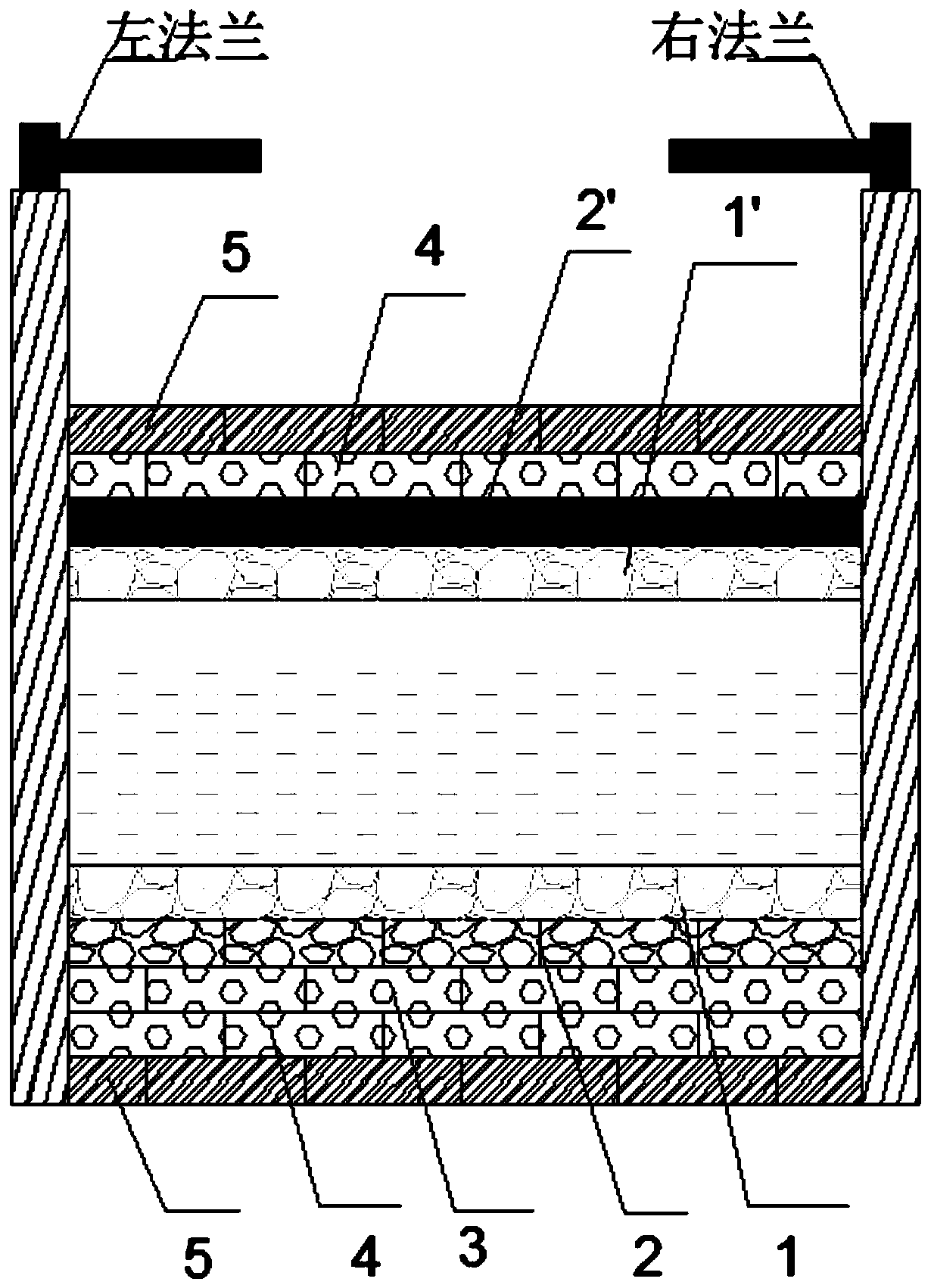
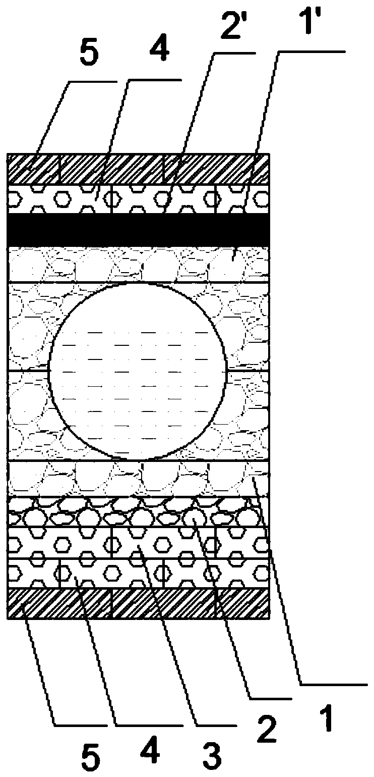
[0049] S1: Install the first U-shaped brick and the second U-shaped brick on the outer wall of the pipeline in the clarification section, and install a heating brick with an S-shaped platinum heating wire inside on the first U-shaped brick as an indirect heating system. The width is 10cm;

[0050] S2: Wrap the second thermal insulation layer and the first thermal insulation layer sequentially on the heating brick described in step S1 from the inside to the outside, and sequentially wrap the fourth thermal insulation layer, the third thermal insulation layer, and the second thermal insulation layer on the second U-shaped brick and the first insulation layer;

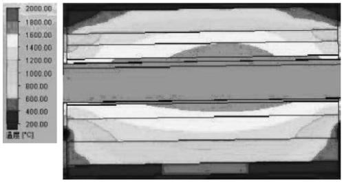
[0051] S3: Control the load power of the heating brick according to the temperature of different areas of the pipeline in the clarification section. When the temperature of the pipeline in the clarification section is 1450°C,...

Embodiment 2

[0053] A temperature control method for a clarification section, comprising the following steps:

[0054] S1: Install the first U-shaped brick and the second U-shaped brick on the outer wall of the pipeline in the clarification section, and install a heating brick with an S-shaped platinum heating wire inside on the first U-shaped brick as an indirect heating system. The width is 15cm;

[0055] S2: Wrap the second thermal insulation layer and the first thermal insulation layer sequentially on the heating brick described in step S1 from the inside to the outside, and sequentially wrap the fourth thermal insulation layer, the third thermal insulation layer, and the second thermal insulation layer on the second U-shaped brick and the first insulation layer;

[0056] S3: Control the load power of the heating bricks according to the temperature in different areas of the pipeline in the clarification section. When the pipeline temperature in the clarification section is 1500°C, con...

Embodiment 3

[0058] A temperature control method for a clarification section, comprising the following steps:

[0059] S1: Install the first U-shaped brick and the second U-shaped brick on the outer wall of the pipeline in the clarification section, and install a heating brick with an S-shaped platinum heating wire inside on the first U-shaped brick as an indirect heating system. The width is 20cm;

[0060] S2: Wrap the second thermal insulation layer and the first thermal insulation layer sequentially on the heating brick described in step S1 from the inside to the outside, and sequentially wrap the fourth thermal insulation layer, the third thermal insulation layer, and the second thermal insulation layer on the second U-shaped brick and the first insulation layer;

[0061] S3: Control the load power of the heating brick according to the temperature of different areas of the pipeline in the clarification section. When the temperature of the pipeline in the clarification section is 1550°...


PUM

PropertyMeasurementUnit
widthaaaaaaaaaa

Abstract

The invention discloses a settling section temperature control device and method. The settling section temperature control device comprises a heat preservation layer on the outer layer and heating sticks on the inner layer, and the relative temperature difference of the settling section is reduced by thinning the heat preservation layer of the outer layer; then the heating sticks on the inner layer are utilized, the manner that large power is loaded on an area with a relatively low temperature, and small power is loaded on an area with a relatively high temperature is adopted, the relative temperature difference of the settling section is furthermore reduced, the purpose that crystal precipitation caused by platinum class melting defects is prevented is achieved, and the purpose of lowering the reject ratio in the production process is achieved.

Description

[0001] 【Technical field】 [0002] The invention belongs to the field of liquid crystal glass manufacturing, and in particular relates to a device and method for reducing the relative temperature difference in a clarification section. [0003] 【Background technique】 [0004] During the production process of TFT glass, the number of melting defects in the glass substrate directly affects its quality. Among melting defects, platinum defects are one of the important factors affecting the quality of glass substrates, and they are also unavoidable melting defects. There are many sources of platinum defects, which can be mainly divided into three aspects: first, platinum in the glass is precipitated or volatilized and recrystallized; second, mechanical friction causes it to fall off; third, it is mixed in glass raw materials. The general solutions mainly include local heating to reduce the temperature difference, design and improve the device to reduce friction, and add a magnetic gr...

Claims


Application Information

Patent Timeline
Patent Type & Authority Patents(China)
IPC IPC(8): C03B5/225
Inventor 侯宏荣孙绪张天文
Owner RAINBOW (HEFEI) LIQUID CRYSTAL GLASS CO LTD
Why Eureka
Try Eureka