
Steel bar truss floor deck

A technology of reinforced trusses and floor slabs, applied in the field of floor slabs, can solve the problems of long construction period, poor quality, cumbersome procedures, etc., and achieve the effects of fast construction progress, saving occupied area, and reducing costs

Inactive Publication Date: 2017-04-19
BEIJING URBAN CONSTR NORTH CONSTR
View PDF8 Cites 5 Cited by
  • Summary
  • Abstract
  • Description
  • Claims
  • Application Information

AI Technical Summary

Problems solved by technology

[0005] The purpose of the present invention is to provide a steel truss floor deck, so as to overcome the shortcomings of the traditional floor construction methods such as poor quality, long construction period, and cumbersome procedures.

Method used


Image

  • Steel bar truss floor deck
  • Steel bar truss floor deck
  • Steel bar truss floor deck

Examples


Embodiment 1

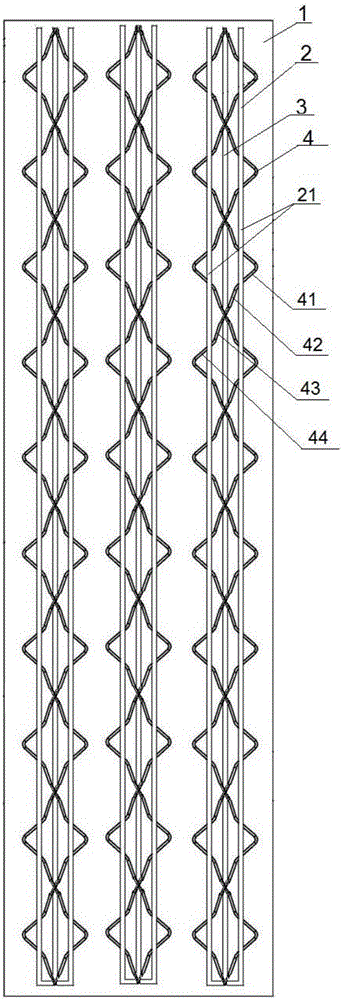
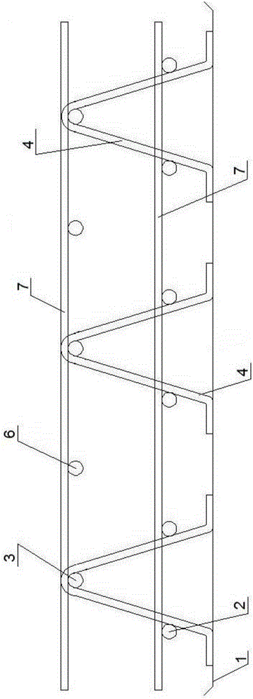
[0025] Such as Figure 1-2 As shown, each reinforcement assembly includes a lower chord 2 , an upper chord 3 and two web reinforcements 4 . There is a certain distance between the lower string member 2 and the top surface of the base plate 1 . The lower chord 2 includes two first steel bars 21 extending parallel to the length direction of the base plate 1 and a first connecting steel bar 22 , the first connecting steel bar 22 is connected to the first ends of the two first steel bars 21 . The upper chord reinforcement 3 is arranged parallel to the first reinforcement 21 , and the upper chord reinforcement 3 is arranged directly above the lower chord 2 , that is, in the middle of the two first reinforcements 21 .

[0026] Such as figure 1 and 2 As shown, each web reinforcement 4 is S-shaped, and the web reinforcement 4 extends from one end of the upper chord reinforcement 3 and the lower chord 2 to the other end, and the web reinforcement 4 is connected to the top surface of...

Embodiment 2

[0032] The difference between this embodiment and Embodiment 1 is that the steel bar assembly includes two lower chords 2 arranged from top to bottom, and the lowermost lower chord 2 has a certain distance from the top surface of the base plate 1, such as Figure 4 shown.

[0033] When utilizing the floor bearing plate of the steel bar truss of the present invention to install, comprise the following steps:

[0034] 1) According to the strength of steel bars designed on engineering drawings, the bearing capacity of the floor and the service life, calculate the steel bar models of the upper chord, lower chord and web reinforcement.

[0035] 2) Process the floor deck.

[0036] 3) Acceptance of materials entering the site: Sampling inspection is carried out on the qualified floor slabs to ensure that the steel bar type and structural dimensions of the floor slabs are correct, and check whether the welding points of the floor slabs are firm.

[0037] 4) Directly hoist the qualif...


PUM


Abstract

The invention discloses a steel bar truss floor deck which comprises a base plate and a plurality of steel bar assemblies. Each steel bar assembly comprises at least one bottom chord piece, an upper chord steel bar and two web member steel bars, wherein each bottom chord piece comprises two parallelly extending first steel bars and a first connecting steel bar which is connected with the first ends of the two first steel bars, and the bottom chord pieces are arranged above the base plate; the upper chord steel bar is arranged above the uppermost bottom chord piece; each web member steel bar is in an S shape, extends from one end of the upper chord steel bar to the other end of the upper chord steel bar, is fixedly connected with the top face of the base plate, the inner sides of the two first steel bars and the upper chord steel bar, and comprises a plurality of steel bar sections, and each steel bar section extends from one side of the upper chord steel bar to the other side of the upper chord steel bar; and the two web member steel bars are separately arranged on the two sides of the same position of the upper chord steel bar. The steel bar truss floor deck is rapid in construction progress, and the occupied area of a workyard is saved.

Description

technical field [0001] The invention relates to the construction field, in particular to a floor bearing plate of a steel bar truss. Background technique [0002] With the development of construction technology, the construction industry has undergone rapid changes. According to the construction technology of the traditional steel truss slab, firstly, the formwork erection and floor formwork installation are carried out to form a steel bar operation and installation platform, and then the steel bar is manually bound and installed on the formwork support system to form the steel bar skeleton of the reinforced concrete floor. Concrete pouring will be carried out after the steel skeleton is accepted, and finally the formwork support system pre-supported will be completely removed according to the form removal time determined by the floor strength of the concrete structure, and other cleaning work will be carried out to finally form the structural floor. [0003] However, the c...

Claims


Application Information

Patent Timeline
IPC IPC(8): E04B5/40E04C5/06
CPCE04B5/40E04C5/06
Inventor 许龙迪王振兴王卫新安然杜普王洪旭王洪乾
Owner BEIJING URBAN CONSTR NORTH CONSTR
Learn More