Method and system for particulate filter leak detection

A particle filter and leakage detection technology, applied in the direction of machine/engine, electronic control of exhaust treatment device, diagnostic device of exhaust treatment device, etc., can solve the problem of sensor contamination, difficulty in reaching sensor regeneration temperature, and inaccurate voltage Questions like readings and current readings

Active Publication Date: 2020-12-04
FORD GLOBAL TECH LLC
View PDF12 Cites 0 Cited by
  • Summary
  • Abstract
  • Description
  • Claims
  • Application Information

AI Technical Summary

Problems solved by technology

As an example, non-uniform or low soot deposition on the surface can occur due to a biased flow distribution across the sensor surface, which results in inaccurate voltage and current readings across the gap
Also, in some sensor designs it may be difficult to reach the sensor regeneration temperature due to the high flow impact on the surface
Furthermore, the sensor can become contaminated due to the impact of large diesel particles or water droplets on the sensor electrode surface

Method used


Image

  • Method and system for particulate filter leak detection
  • Method and system for particulate filter leak detection
  • Method and system for particulate filter leak detection

Examples


Embodiment Construction

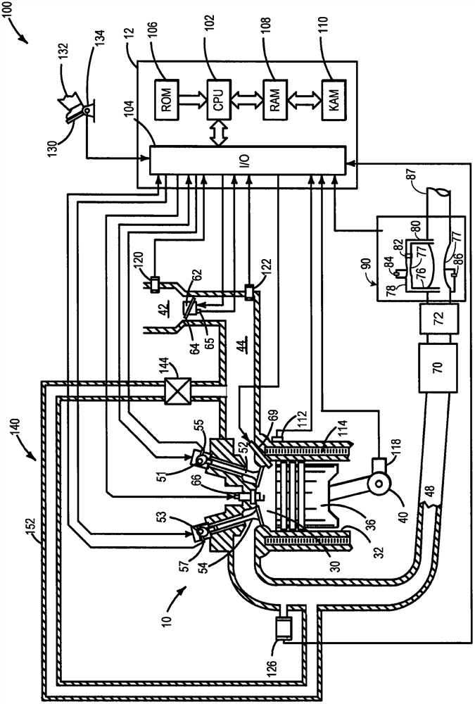
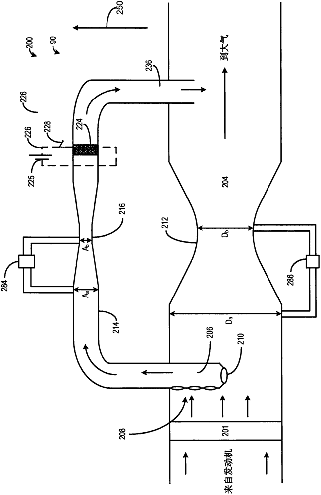
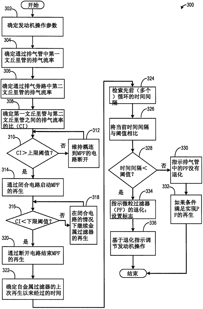
[0013] The following description relates to systems and methods for determining exhaust DPF degradation based on an exhaust flow rate-based soot sensor coupled downstream of the DPF. figure 1 A vehicle system is shown including an engine configured to operate on a fuel such as diesel. The DPF is disposed in the main exhaust pipe, and downstream of the DPF, a second soot sensor assembly is positioned to detect particulates leaking from the DPF. Such as figure 2 As shown, the second soot sensor assembly may include an exhaust bypass parallel to the exhaust pipe fitted with a metal filter and associated electrical circuitry. Two or more sensors are provided for measuring the pressure drop across respective venturis of the exhaust pipe and exhaust bypass. The engine controller is configured to conduct control routines such as image 3 The example routine in to regenerate a metal filter based on the estimated exhaust flow rate ratio between the two venturis and diagnose the DPF...


PUM


Abstract

The present application provides methods and systems for determining particulate filter degradation in an exhaust line. In one example, the method may include diverting the exhaust gas to a second soot sensor assembly including a second filter downstream of the first filter, and subsequent filtering based on the second filter in the second soot sensor assembly The time interval between generator regenerations determines degradation.

Description

technical field [0001] This specification generally relates to the design and use of sensors for diagnosing diesel particulate filters (DPF). Background technique [0002] Engine combustion may generate particulate matter (PM) such as soot and aerosols that may be emitted into the atmosphere. For emissions compliance, a particulate matter filter, such as a diesel particulate filter (DPF) or gasoline particulate filter (GPF), may be included in the engine exhaust to filter out PM before releasing the exhaust gas to the atmosphere. Additionally, one or more soot sensors may be used to diagnose the DPF and such soot sensors may be coupled upstream and / or downstream of the DPF. [0003] Also, various types of soot sensors have been developed to sense the generation and release of soot. One exemplary approach, shown in US 8,310,249 by Paterson, discloses a soot sensor that collects particulate matter on charged electrodes. A soot sensor consists of opposing electrodes separate...

Claims


Application Information

Patent Timeline
Patent Type & Authority Patents(China)
IPC IPC(8): F01N9/00F01N11/00
CPCF01N9/002F01N11/00F01N2550/12F01N2470/30F01N11/002F01N3/021F01N3/0275F01N3/023F01N3/005F01N2560/08F01N2550/04F01N2900/0408Y02T10/40
Inventor 张小钢
Owner FORD GLOBAL TECH LLC
Why Eureka
Try Eureka