Refrigerant filling machine and method for carrying out vacuum-pumping, leakage detecting and refrigerant filling by utilizing refrigerant filling machine

A filling machine and vacuuming technology, used in lighting and heating equipment, refrigerators, refrigeration and liquefaction, etc., can solve the problems of high professional proficiency, cumbersome operation process, hidden safety hazards, etc., to improve system reliability, The effect of prolonging the vacuuming time and saving manpower and material resources

Inactive Publication Date: 2017-04-19
ZHEJIANG VALUE MECHANICAL & ELECTRICAL PROD CO LTD
View PDF8 Cites 25 Cited by
  • Summary
  • Abstract
  • Description
  • Claims
  • Application Information

AI Technical Summary

Problems solved by technology

[0003] The present invention mainly provides a refrigerant filling machine that saves time and effort, saves manpower and material resources, and integrates multiple functions and uses the equipment for vacuuming, leak detection and refrigerant filling methods, which solves the problems in the prior art. There are a series of conversi...

Method used


Image

  • Refrigerant filling machine and method for carrying out vacuum-pumping, leakage detecting and refrigerant filling by utilizing refrigerant filling machine
  • Refrigerant filling machine and method for carrying out vacuum-pumping, leakage detecting and refrigerant filling by utilizing refrigerant filling machine

Examples


Embodiment

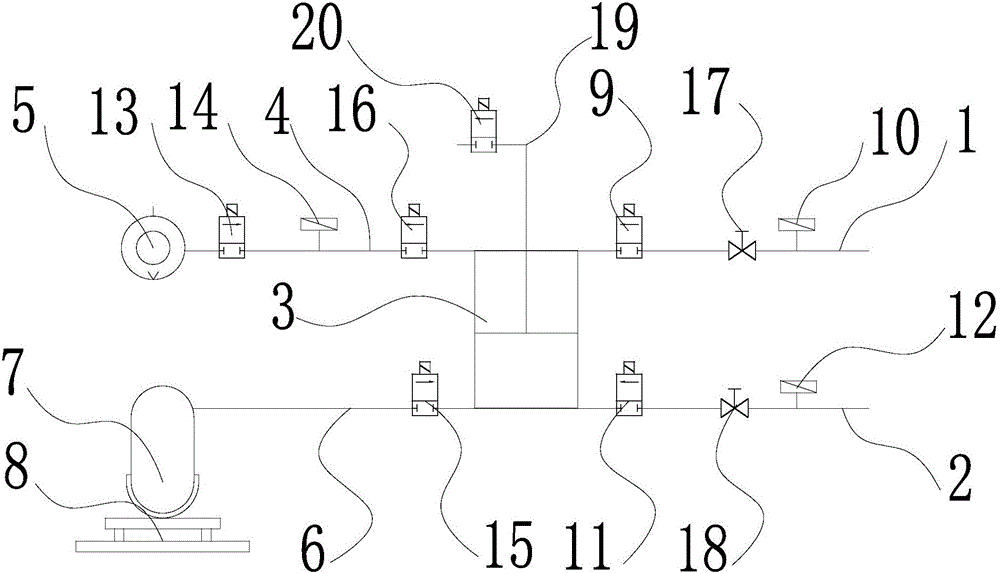
[0041] Such as figure 1 As shown, a refrigerant filling machine of the present invention includes a corresponding high-pressure pipe 1 and a low-pressure pipe 2 connected to the high and low-pressure ends of the refrigeration system, and the other ends of the high-pressure pipe 1 and the low-pressure pipe 2 are connected in parallel. On the interface of one end of the valve body pipeline 3, the other end of the valve body pipeline 3 is connected in parallel to the vacuum pipeline 4 and the refrigerant pipeline 6, and the other end of the vacuum pipeline 4 is connected to the vacuum pump 5 and the refrigerant pipeline 6. The other end is connected to the refrigerant storage cylinder 7. The refrigerant storage cylinder 7 is placed on the electronic scale 8. On the high-pressure pipeline 1, there are a high-pressure side solenoid valve 9 and a high-pressure side sensor 10 in series. The valve 9 is located on the high-pressure pipeline 1 close to the valve body pipeline 3, and a hig...


PUM


Abstract

The invention discloses a refrigerant filling machine, and provides a refrigerant filling machine, which is time-saving and labor-saving in operation, saves manpower and material resources, and integrates multiple functions, and a method for carrying out vacuum-pumping, leakage detecting and refrigerant filling by utilizing the refrigerant filling machine. The refrigerant filling machine solves the technical problems that manual independent operation is needed, an operation process is complex, time and labor are wasted, misoperation is extremely liable to generate, certain potential safety hazards exist and the like in the prior art. The refrigerant filling machine comprises a high-pressure pipeline and a low-pressure pipeline which are correspondingly connected to a high-pressure end and a low-pressure end of a refrigerating system, wherein the other end of the high-pressure pipeline and the other end of the low-pressure pipeline are connected to one end of a valve body pipeline in parallel correspondingly; the other end of the valve body pipeline is connected with a vacuum pipeline and a refrigerant pipeline in parallel; the other end of the vacuum pipeline is connected with a vacuum pump; the other end of the refrigerant pipeline is connected with a refrigerant storage steel cylinder; the refrigerant storage steel cylinder is placed on an electronic scale; solenoid valves capable of controlling on-off of corresponding pipelines are arranged on the pipelines; and the solenoid valves and the electronic scale are connected onto a control system.

Description

Technical field [0001] The invention relates to a refrigerant filling machine, in particular to a refrigerant filling machine that saves time and effort in operation, saves manpower and material resources, and integrates multiple functions and a method for vacuuming, leak detection and refrigerant filling with the equipment. Background technique [0002] Refrigeration systems often need regular cleaning and maintenance. However, if the drying is not thorough after cleaning, a certain amount of water will inevitably remain in the pipes of the refrigeration system. If there is water in the pipes, the throttling mechanism and low pressure of the refrigeration system must be Part of the "ice plug" causes the refrigeration system to fail to work normally. Therefore, before the refrigerant is filled, the refrigeration system is often brought to a vacuum state through a vacuum pump to effectively remove the water in the refrigeration system. Corrosion, loosening and leakage of related p...

Claims


Application Information

Patent Timeline
IPC IPC(8): F25B45/00F25B49/00
CPCF25B45/00F25B49/00F25B49/005
Inventor 蒋友荣
Owner ZHEJIANG VALUE MECHANICAL & ELECTRICAL PROD CO LTD
Why Eureka
Try Eureka