Rotary vibration damping arrangement

A technology of torsional vibration damping and torsional vibration, applied in the direction of rotational vibration suppression, vibration suppression adjustment, spring/shock absorber, etc., to reduce load, prevent collision, and improve friction.

Inactive Publication Date: 2017-04-19
ZF FRIEDRICHSHAFEN AG
View PDF7 Cites 0 Cited by
  • Summary
  • Abstract
  • Description
  • Claims
  • Application Information

AI Technical Summary

Problems solved by technology

On the other hand, due to the very high torques introduced and / or due to the excitation in the range of the natural frequency of the torsional vibration damping assembly, such an overload of the torsional vibration damping assembly can thus occur.

Method used


Image

  • Rotary vibration damping arrangement
  • Rotary vibration damping arrangement
  • Rotary vibration damping arrangement

Examples


Embodiment Construction

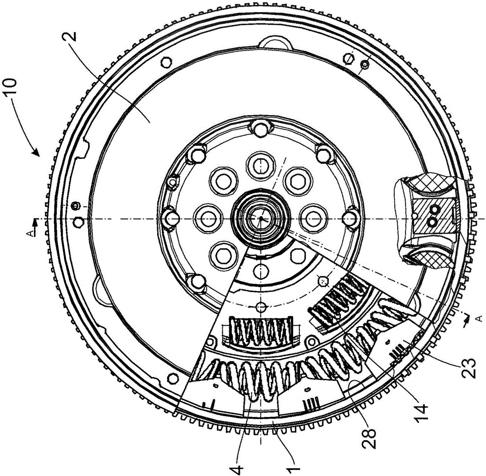
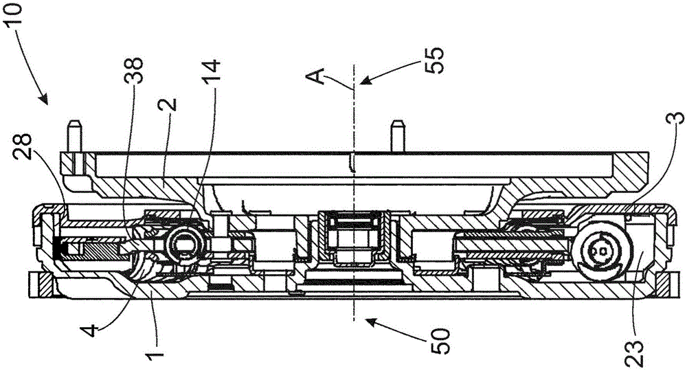
[0039] figure 1 with figure 2 A torsional vibration damping arrangement 10 in the form of a two-row dual-mass flywheel is shown as prior art. In this case, the primary mass 1 in the input region 50 can overcome the first spring assembly 4 and the second spring assembly 14 (viewed around the axis of rotation A, the second spring assembly is positioned radially inside the first spring assembly and connected in series) rotate relative to the secondary mass 2 in the output region 55 . In this case, the primary mass 1 forms, in the radially outer region, a sliding surface 28 on which the sliding element 23 can slide about the axis of rotation A in the circumferential direction. In this case, the sliding element 23 accommodates the outer spring assembly 4 and supports it in the radial direction and in the axial direction. Depending on the centrifugal force occurring, which in turn depends on the rotational speed of torsional vibration damper arrangement 10 , the frictional pr...


PUM


Abstract

Rotary vibration damping arrangement (10, 11, 12), in particular for the drive train of a motor vehicle, comprising a primary mass (1) having a radially inward oriented sliding surface (28), a secondary mass (2) and an energy storage device (5), wherein the energy storage device comprises at least one spring arrangement (4) and a sliding element (23), wherein the primary mass can be rotated about a common axis of rotation (A) relative to the secondary mass and against a resistance of the energy storage device, and wherein a radial outer sliding surface (24) of the sliding element of the energy storage device is oriented toward the radially inward oriented sliding surface of the primary mass, wherein the sliding surface of the primary mass and / or an adjacent sliding surface of the primary mass and / or an adjacent sliding surface of a cover sheet (3) comprises at least one magnet element (17, 54, 59) and the sliding element of the energy storage device comprises a magnet element (59).

Description

technical field Background technique [0001] In the field of vehicle construction, and here in particular in the field of motor vehicle construction, it is a recurring problem that torsional vibrations can occur in the drive train of a vehicle. Torsional vibrations can lead to a mechanical stress on the components of the drive train and also to a reduction in the driving comfort of the corresponding vehicle. [0002] For example, in principle an internal combustion engine does not generate a constant torque and a constant rotational speed per revolution of the crankshaft. These two parameters fluctuate depending on the operating state, so that rotational inhomogeneities can occur at the crankshaft of such an internal combustion engine. For most applications, however, a torque and speed profile that is as constant as possible is in principle sought. In the case of such applications, therefore, additional systems for reducing the rotational inhomogeneity are usually envisaged...

Claims


Application Information

Patent Timeline
IPC IPC(8): F16F15/131F16F15/134F16F15/18
CPCF16F15/13157F16F15/13453F16F15/18
Inventor D·洛伦茨
Owner ZF FRIEDRICHSHAFEN AG
Why Eureka
Try Eureka