Tool for pocket hole of short cylindrical roller bearing retainer and pocket hole method thereof

A bearing cage and short cylindrical roller technology, which is applied in broaching equipment, manufacturing tools, metal processing equipment, etc., can solve the inconsistency of the pocket axial position and the accuracy of the pocket circumferential position and affect the machining of the cage. quality and other issues, to achieve the effect of improving bearing performance and reliability, solving accuracy stability and consistency problems, and facilitating positioning

Active Publication Date: 2017-04-26
AVIC HARBIN BEARING
View PDF11 Cites 7 Cited by
  • Summary
  • Abstract
  • Description
  • Claims
  • Application Information

AI Technical Summary

Problems solved by technology

[0006] The purpose of the present invention is to solve the problem that the accuracy of the axial position of the pocket hole and the circumferential position of the pocket hole is inconsistent due to the repeated disassembly and assembly of the cage by the existing drawing square hole tooling, thereby affecting the processing quality of the cage

Method used


Image

  • Tool for pocket hole of short cylindrical roller bearing retainer and pocket hole method thereof
  • Tool for pocket hole of short cylindrical roller bearing retainer and pocket hole method thereof

Examples


specific Embodiment approach 1

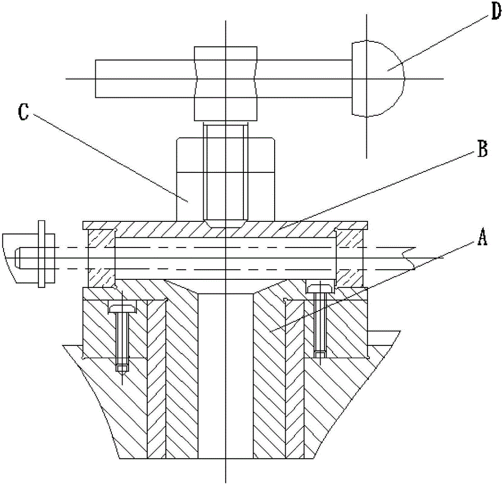
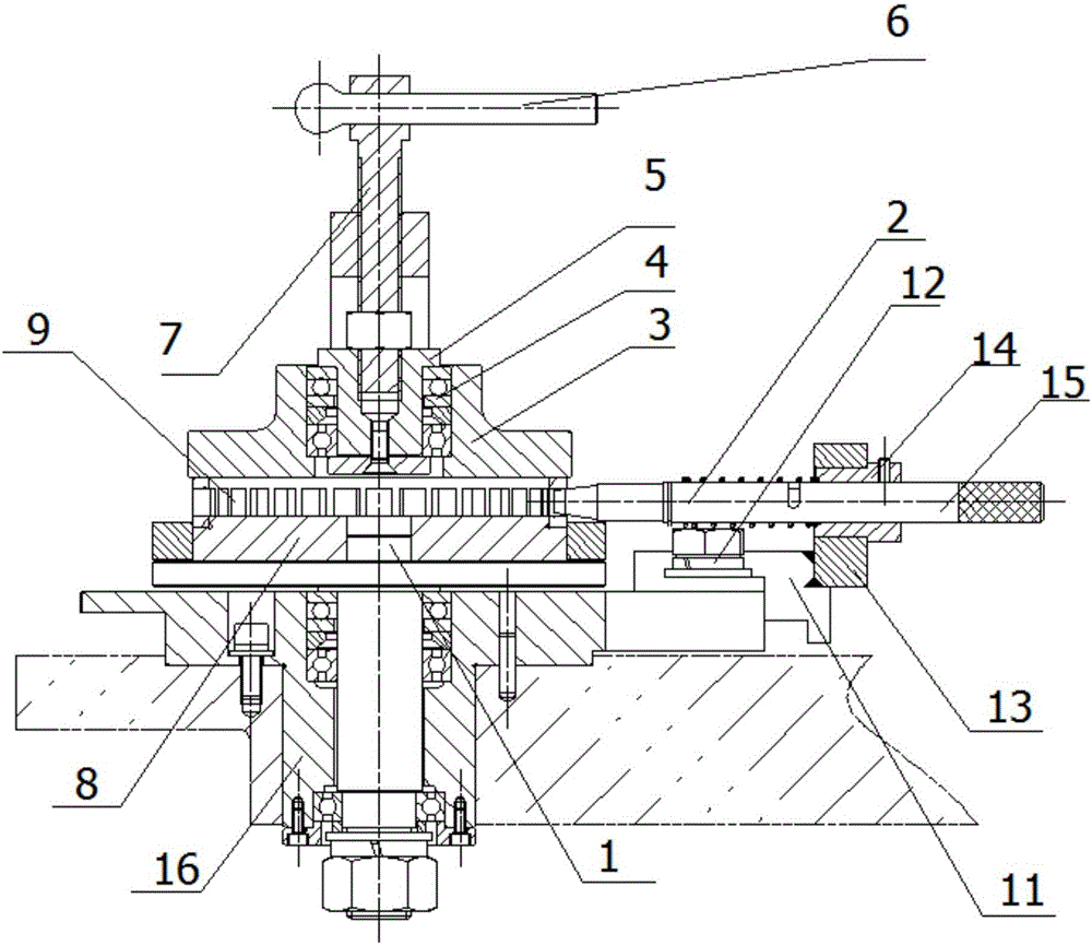
[0036] Specific implementation mode one: combine figure 2 Describe this embodiment, a short cylindrical roller bearing cage pocket tooling of this embodiment, which includes a positioning rotating shaft 1, a positioning pin 2, a cover plate 3, a pressing block 5, a tightening rod 6, and a pressing rod 7 And the positioning shaft 8, the positioning shaft 8 can be rotatably installed on the workbench, the positioning rotating shaft 1 is set in the center hole on the positioning shaft 8, the cage 9 is installed on the positioning shaft 8, and the cover plate 3 is press-fitted on the cage 9 Above, there is a stepped hole in the middle of the cover plate 3, the pressure block 5 is rotatably installed in the stepped hole of the cover plate 3, the pressure rod 7 is screwed vertically in the pressure block 5, and the tightening rod 6 is horizontally installed on the pressure rod 7, the positioning pin 2 is detachably inserted in any pocket of the cage 9.

specific Embodiment approach 2

[0037] Specific implementation mode two: combination figure 2 This embodiment is described. This embodiment also includes a plurality of bearings 4 , and the pressure block 5 is connected to the cover plate 3 through the plurality of bearings 4 installed in the stepped holes. Such arrangement facilitates the smooth press-fitting and fixing of the pressing block 5 to the cage through the cover plate, saves labor intensity for the operator, and improves the press-fitting efficiency at the same time. Other compositions and connections are the same as in the first embodiment.

specific Embodiment approach 3

[0038] Specific implementation mode three: combination figure 2 Describe this embodiment, this embodiment also includes a positioning pin transmission assembly, the positioning pin transmission assembly includes a fixed base 11, a support frame 12, a feed seat 13, a feed sleeve 14 and a transmission rod 15, and the support frame 12 and the fixed base 11 are in turn Installed on the workbench, and the support frame 12 is installed close to the side of the positioning shaft 8, a working hole is opened horizontally on the feed seat 13, the feed seat 13 is installed on the fixed base 11, and the feed sleeve 14 is inserted into the feed seat 13 In the working hole, the transmission rod 15 is set on the support frame 12 after passing through the feed sleeve 14, and the end of the transmission rod 15 near the support frame 12 side is connected with the non-insert end of the positioning pin 2. Such setting not only facilitates the positioning and installation of the positioning pin, ...


PUM


Abstract

The invention provides a tool for a pocket hole of a short cylindrical roller bearing retainer and a pocket hole method of the tool, relates to a tool for the pocket hole and the pocket hole method of the tool, and aims to solve the problem that due to the inconsistency between the axial position degree and the circumferential position degree of the pocket hole, the processing quality of the retainer is affected. According to the tool, a locating shaft is installed on a workbench in a rotatable mode, a locating rotating shaft is installed in a center hole formed in the locating shaft in a sleeved mode, and the retainer is installed on the locating shaft; a cover plate is installed on the retainer in a press mode, a stepped hole is formed in the middle of the cover plate, and a press block is installed in the stepped hole of the cover plate in a rotatable mode; and a press rod is vertically screwed into the press block, a screwing rod is horizontally arranged at the upper end of the press rod in a penetrating mode, and a locating pin is detachably inserted into the pocket hole of the retainer. The method comprises the steps that the tool for the pocket hole of the retainer is installed; the retainer is fixed; the position of the pocket hole to be broached is determined; the work of preparation before broaching is conducted; after a broaching machine is started, broaching of the pocket hole is accomplished; and broaching is conducted repeatedly until broaching of the pocket hole of the retainer is accomplished. The tool for the pocket hole and the pocket hole method of the tool are used for production of the bearing retainer.

Description

technical field [0001] The invention relates to a tooling for pocket holes in a cage and a pocketing method thereof, in particular to a tooling for pocket holes in a cage of a short cylindrical roller bearing and a pocketing method thereof. Background technique [0002] The solid cage of short cylindrical roller bearings is machined, and the pocket holes are generally processed by broaching. There are many factors that affect the machining accuracy of the pocket hole, including the material, structure, and manufacturing quality of the broach, the tooling structure and manufacturing quality of the broaching square hole, the choice of cutting fluid, the stability of the broaching machine, the determination of working parameters, and operator skills. So far, systematic research has been carried out on broaches, process flow, cutting fluid application, cutting parameters, etc., and the accuracy indicators of this type of cage pockets have been greatly improved. Through the analy...

Claims


Application Information

Patent Timeline
Patent Type & Authority Applications(China)
IPC IPC(8): B23D41/02
CPCB23D41/02
Inventor 李迎丽徐雷孙慧广王涛张凯锐刘伟张宇李宝玉范继承朱磊武伟
Owner AVIC HARBIN BEARING
Why Eureka
Try Eureka