
Plastic pipe cutting device with receiving barrel

A cutting device and plastic pipe technology, applied in metal processing, etc., can solve problems such as poor automation, low cutting efficiency, and reduced cutting quality, and achieve the effects of easy collection, avoiding cutting deviation, and improving cutting efficiency

Inactive Publication Date: 2017-04-26
郑州吉音动漫科技有限公司
View PDF0 Cites 0 Cited by
  • Summary
  • Abstract
  • Description
  • Claims
  • Application Information

AI Technical Summary

Problems solved by technology

[0002] Plastic is a polymer compound made of a monomer as a raw material through addition polymerization or polycondensation reaction. It is commonly known as plastic or resin, and its composition and shape can be changed freely; the so-called plastic is actually a kind of synthetic resin. Pine resin in natural resin is similar to pine resin, which is artificially synthesized by chemical means, and is called plastic; various plastic products can be seen everywhere in modern society. It can be said that plastic is already an indispensable material in our life. It is more and more widely used in our society, among which plastic pipes exist everywhere in our life. Plastic pipes need to be cut according to the requirements of use. Now the cutting of plastic pipes is generally cut with a general-purpose cutting machine, but the cutting efficiency is low. , the cutting accuracy is poor, the degree of automation is poor, and it cannot meet the processing and use requirements of the current society; in the process of cutting plastic pipes, the cutting deviation is often caused because the plastic pipe cannot be fixed, which reduces the quality of cutting

Method used


Image

  • Plastic pipe cutting device with receiving barrel
  • Plastic pipe cutting device with receiving barrel
  • Plastic pipe cutting device with receiving barrel

Examples


Embodiment Construction

[0017] The technical solution of this patent will be further described in detail below in conjunction with specific embodiments.

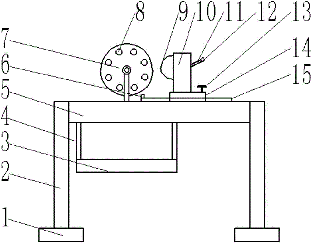
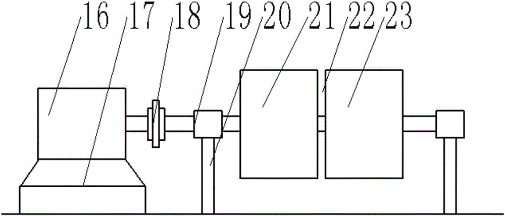
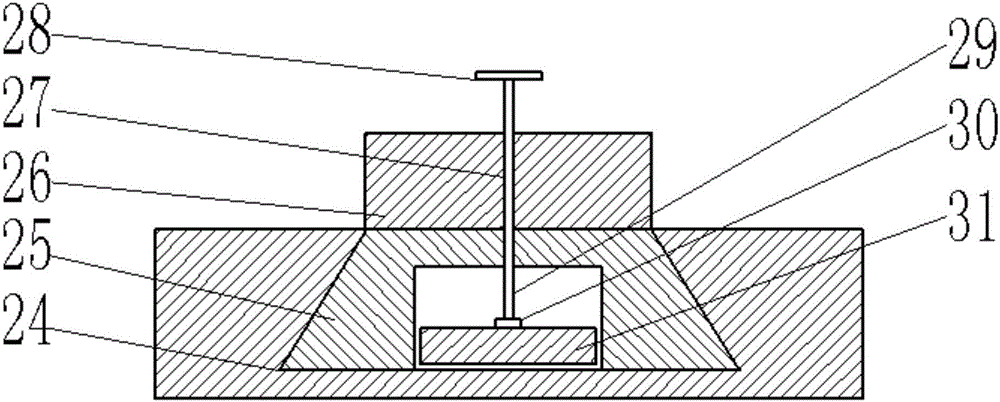
[0018] see Figure 1-4 , a plastic pipe cutting device with a receiving bucket, comprising a workbench 5, a support device 7 and a cutting knife 9; two ends of the workbench 5 are provided with support legs 2, and the bottom of the support legs 2 is provided with a bottom plate 1 , used to increase the contact area of ​​the supporting legs 2, and then support the workbench 5; the support device 7 is arranged on the left part of the upper surface of the workbench 5, and the support device 7 is composed of a motor 16, a bearing 17, a shaft coupling 18, Rotating shaft 19, pillar 20, first support block 21, slit 22, second support block 23 and through hole 8 are formed, are used for fixing the plastic pipe to be cut; Described support 17 is fixed on the workbench 5, and support 17 The top is fixed with a motor 16, the main shaft of the motor 16 is pro...


PUM


Abstract

The invention provides a plastic pipe cutting device with a receiving barrel. The device comprises a worktable, a support device and a cutter; support legs are arranged at two ends of the worktable; the support device consists of a motor, a bracket, a coupling, a rotating shaft, a support column, a first support block, a gap, a second support block and a through hole; a connecting rod is arranged on the worktable at the lower part of the support device, and is provided with the receiving barrel; the cutter is arranged on a cutting machine; the cutting machine is fixed on a slide block; the slide block is placed in a slide rail; a fastening device is arranged on the slide block; the slide block consists of a square block and a dovetail block; the fastening device consists of a thread hole, a rotating handle, a thread rod, a connecting piece and a fastening block; and the connecting piece consists of a shell, a bearing, a fixed end and a sealing ring. The device can stably fix plastic pipes to prevent the cutting deviation, meanwhile, improves the cutting efficiency, can receive the cut plastic pipes, and is convenient to collect the plastic pipes.

Description

technical field [0001] The invention relates to a plastic pipe cutting device, in particular to a plastic pipe cutting device with a material receiving bucket. Background technique [0002] Plastic is a polymer compound made of a monomer as a raw material through addition polymerization or polycondensation reaction. It is commonly known as plastic or resin, and its composition and shape can be changed freely; the so-called plastic is actually a kind of synthetic resin. Pine resin in natural resin is similar to pine resin, which is artificially synthesized by chemical means, and is called plastic; various plastic products can be seen everywhere in modern society. It can be said that plastic is already an indispensable material in our life. It is more and more widely used in our society, among which plastic pipes exist everywhere in our life. Plastic pipes need to be cut according to the requirements of use. Now the cutting of plastic pipes is generally cut with a general-purp...

Claims


Application Information

Patent Timeline
Patent Type & Authority Applications(China)
IPC IPC(8): B26D1/02B26D7/06B26D7/32B26D7/01B26D7/26B26D5/02
CPCB26D1/02B26D5/02B26D7/01B26D7/06B26D7/2614B26D7/32B26D2007/013
Inventor 不公告发明人
Owner 郑州吉音动漫科技有限公司
Learn More