
Centrifugal rotation feeder

A technology of rotary feeder and hopper, applied in the field of mechanical processing, can solve the problems of low efficiency in discharging workpieces, slow feeding speed and difficulty, and achieve the effect of improving efficiency, avoiding re-accumulation and fast feeding speed.

Inactive Publication Date: 2017-04-26
GUANGXI UNIV FOR NATITIES
View PDF1 Cites 4 Cited by
  • Summary
  • Abstract
  • Description
  • Claims
  • Application Information

AI Technical Summary

Problems solved by technology

But there are also shortcomings: there is a chute on the side wall of the loading hopper for the high-speed rotating workpiece to enter, which is a bit difficult, and the workpiece often cannot accurately enter the chute, resulting in low efficiency of discharging the workpiece, and thus slow feeding speed; It is set along the tangential direction of rotation, which means that the inlet and outlet ends of the chute are on the same level, which is not conducive to the workpiece sliding out; this device is only for the conveying of cylindrical workpieces, and the feeding is single

Method used


Image

  • Centrifugal rotation feeder

Examples


Embodiment Construction

[0013] The present invention will be described in further detail below by means of specific embodiments:

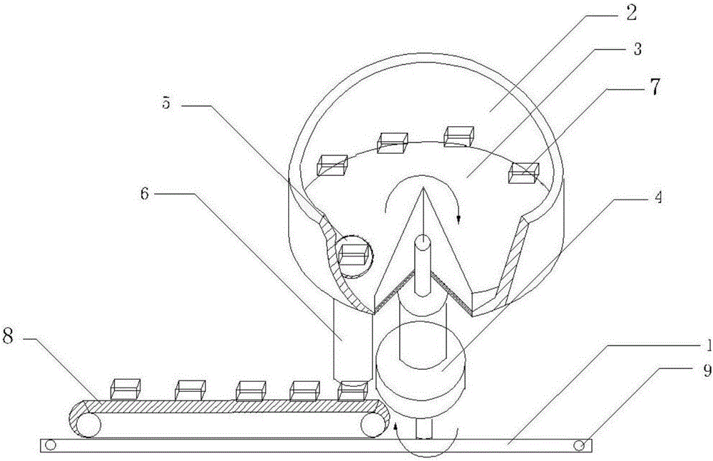
[0014] The reference signs in the drawings of the description include: machine base 1, hopper 2, cone 3, bearing 4, hole 5, conduit 6, workpiece 7, belt conveyor 8, threaded hole 9.

[0015] Example basic reference figure 1 Shown: Centrifugal rotary feeder, including machine base 1, hopper 2, cone 3, bearing 4 and conduit 6, cone 3 is arranged in hopper 2, and the bottom surface of hopper 2 is the bottom of cone 3, the bottom surface The top of the center is the apex, the lower end of the center of the cone 3 is connected to the bearing 4, the bearing 4 is installed on the base 1, and the bearing 4 drives the hopper 2 to rotate, and a hole 5 is opened at the edge of the bottom of the cone 3, and the bottom of the hole 5 is connected Conduit 6 is arranged, and belt conveyor 8 is installed below conduit 6, and its belt conveyor 8 is installed on the support 1.

[0016] Wh...


PUM


Abstract

The invention relates to the technical field of machining, and discloses a centrifugal rotation feeder. Compared with the prior art, the centrifugal rotation feeder is fast, accurate and stable in feeding and capable of conveying workpieces in different shapes. The centrifugal rotation feeder comprises a machine seat, a hopper, a cone, a bearing and a guide pipe, wherein the cone is arranged in the hopper; the bottom surface of the hopper is a cone rotary bottom, and the vertex is arranged above the center of the bottom surface; the lower end of the center of the cone is connected with the bearing; the bearing is installed on the machine seat and drives the hopper to rotate; and a hole is formed in the edge of the cone rotary bottom, the guide pipe is connected under the hole, and a belt conveyer is installed under the guide pipe and installed on the machine seat.

Description

technical field [0001] The invention relates to the technical field of mechanical processing, in particular to a centrifugal rotary feeder. Background technique [0002] At present, the common workpiece feeder is a vibrating type, which makes a lot of noise when vibrating, causing noise pollution, unstable operation, and slow feeding speed. [0003] The patent document with the application number 201220670444.2 discloses a centrifugal feeding device, which includes a hopper, the hopper is composed of a bottom surface and a side wall, the lower end of the hopper is connected to a rotating shaft supported on a bearing, and the rotating shaft drives the hopper Rotate, the bottom surface of the charging hopper is a conical rotating bottom, the center of the bottom surface is the apex, and the side wall of the charging hopper is provided with a chute along the tangential direction of its rotation, and the workpiece can slide into the chute when the loading hopper rotates. Althou...

Claims


Application Information

Patent Timeline
Patent Type & Authority Applications(China)
IPC IPC(8): B65G47/14B65G29/00
CPCB65G47/1435B65G29/00
Inventor 王雪
Owner GUANGXI UNIV FOR NATITIES
Learn More