Easy-tear cap production line and manufacturing method

An easy-tear cover and production line technology, applied in other household appliances, household appliances, applications, etc., can solve the problems of slow production speed, high scrap rate, inability to achieve high-speed production, etc., and achieve the effect of convenient maintenance and pressure reduction.

Active Publication Date: 2018-02-02
HANGZHOU SHANGJING MACHINERY CO LTD
View PDF4 Cites 4 Cited by
  • Summary
  • Abstract
  • Description
  • Claims
  • Application Information

AI Technical Summary

Problems solved by technology

[0004] The disadvantages of the above two prior patent applications: the handling method of the lid in the disclosed easy-tear lid equipment is realized by two motors, one of which drives the crank linkage mechanism to drive the carrier to reciprocate, and the other motor Drive a horizontal long axis to drive the up and down movement of the transport frame, so as to realize the back and forth transport mode of lifting-forward-down-retracting of the cover. This transport mode has a slow production speed and cannot achieve high-speed production.
Its shortcoming: the application implements the cover handling method in the form of two sets of synchronous belts at the front and rear plus a turning disc, because the turning disc is added in the middle (such as Figure 5 As shown, 27 in the figure is the turning plate), not only the structure of the turning plate is complicated, the adjustment is very difficult, but also the cover is easily scratched when it rubs into the slot of the turning plate, and the scrap rate is high

Method used


Image

  • Easy-tear cap production line and manufacturing method
  • Easy-tear cap production line and manufacturing method
  • Easy-tear cap production line and manufacturing method

Examples


Embodiment 1

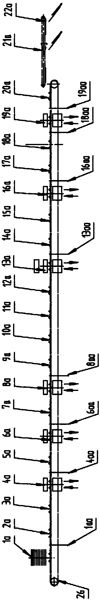
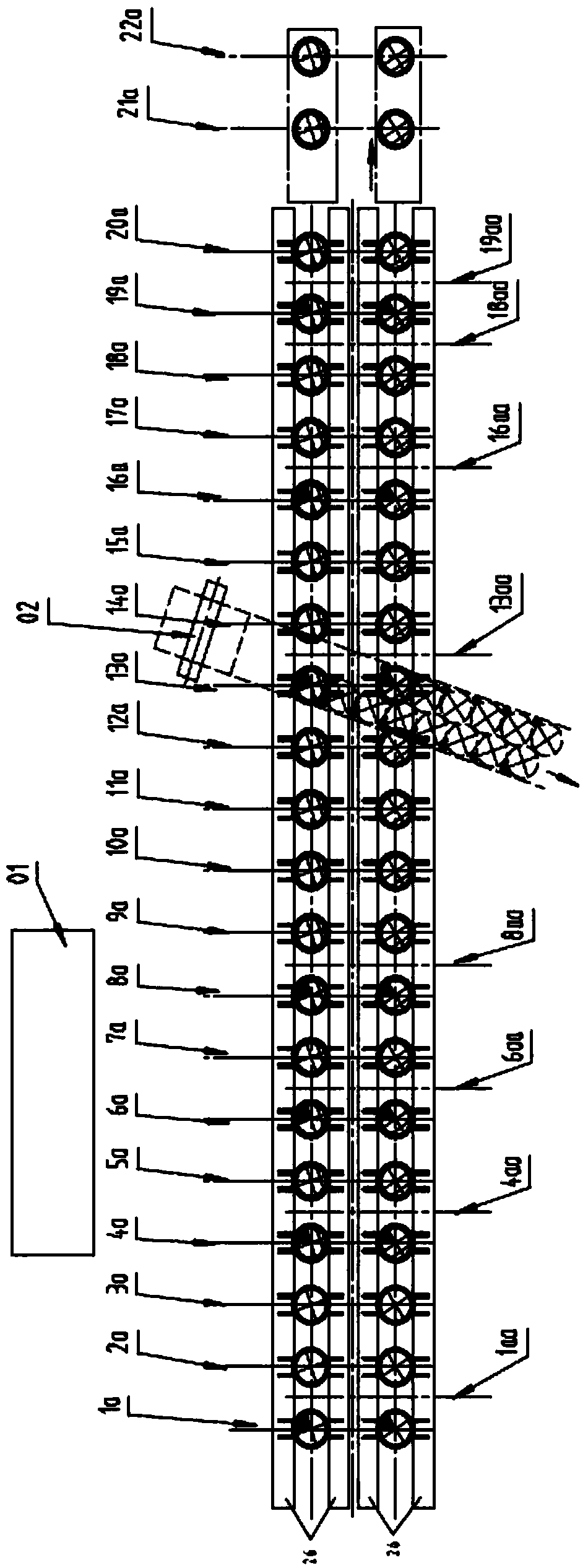
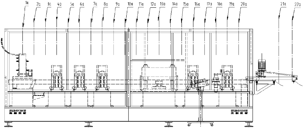
[0070] Embodiment 1: with reference to attached Figure 1-25 . An easy-tear cap production line 1, including an electric control box 01, an aluminum foil or film unwinding device 02, a synchronous belt conveying mechanism 26 (one or more groups of synchronous belt conveying mechanisms are arranged side by side), a sub-lid and a lower cap device 1a , middle hole forming device (4a, 6a, 8a), preheating device 10a-12a, punching aluminum foil or film and pre-sealing device 13a, heat sealing device 16a, cooling and handle alignment device 18a, folding handle device 18aa, pressing Flower or flattening device 19a, sealing defective product discharge device 21a, finished product output device 22a: in the sub-cover and lower cover device 1a: a. A turning cylinder 313 is added between the mounting plate 311 and the lower cover frame 312; b. The sub-cover screwdriver is composed of a body 31a, a cutter head 31b, and a gasket 31c. By adjusting the thickness of the gasket 31c, the height ...

Embodiment 2

[0077]Embodiment 2: On the basis of Embodiment 1, when manufacturing an easy-tear cover with a pull ring or a glued handle, the folding handle device 18aa is placed behind the embossing or flattening device 19a, and the handle fixing device 20a is added and the handle is fixed The device 20a is located behind the folding handle device 18aa.

Embodiment 3

[0078] Embodiment 3: On the basis of Embodiment 1, the lower aligning plate 83 can be made into a D-shaped groove to correspond to the D-shaped curling of the D-shaped cover.


PUM


Abstract

The invention relates to a production line and a manufacturing method of easy-to-tear covers. The production line comprises an electric control box, an aluminum foil or film unwinding device, synchronous belt type carrying mechanisms, a cover separating and discharging device, middle hole forming devices, preheating devices, an aluminum foil or film punching and pre-sealing device, a hot sealing device, a cooling and handle aligning device, a handle folding device, an embossing or flattening device, a defective seal product discharging device and a finished product output device, wherein in the cover separating and discharging device, a, a turnover cylinder is added between a mounting plate and a lower cover frame; b, each cover separating screwdriver comprises a body, a screwdriver head and a gasket, and the spiral groove height of the starting part of the cover separating screwdriver can be adjusted by adjusting the thickness of the gasket; cover falling prevention devices are arranged on the synchronous belt type carrying mechanisms of the middle hole forming devices, the hot sealing device, the cooling and handle aligning device and an embossing and handle fixing device; induction heating is adopted in at least one position in the preheating devices before aluminum foil pre-sealing; a cooling water channel is additionally arranged in an upper mounting plate of the embossing or flattening device.

Description

technical field [0001] The invention relates to an easy-tear cap production line capable of high-speed manufacturing of easy-tear caps, avoiding frictional damage to the caps, and having a high rate of genuine products and a production method, belonging to the field of easy-tear cap production line manufacturing. Background technique [0002] CN103459061B, title "Manufacturing apparatus and method for tearing off caps", which comprises a conveyor for cap elements and caps and a plurality of processing stations for cap elements and caps arranged along the conveyor, said processing stations comprising: A sealing station (5), which is configured to seal the film portion (25) comprising the tear-off tab (29) on a cover element formed as a cover ring (20' ); and a bending station (7), at In this bending station, the tear-off tab (29) can be bent towards the upper side of the film part; it is characterized in that a gluing station (40) is arranged between the sealing station and t...

Claims


Application Information

Patent Timeline
Patent Type & Authority Patents(China)
IPC IPC(8): B21D51/44
CPCB21D51/443
Inventor 孙建锋
Owner HANGZHOU SHANGJING MACHINERY CO LTD
Why Eureka
Try Eureka