
Deslagging structure and deslagging method for water seal tank of rotary hearth furnace

A technology for water-sealing tanks and rotary hearth furnaces, applied in the directions of furnaces, furnace types, furnace components, etc., can solve problems such as the ineffective operation of rotary hearth furnaces, and achieve the effects of reasonable structure, thorough slag discharge, and simple operation.

Active Publication Date: 2021-03-12
SHAGANG GROUP +1
View PDF6 Cites 1 Cited by
  • Summary
  • Abstract
  • Description
  • Claims
  • Application Information

AI Technical Summary

Problems solved by technology

[0006] The purpose of the present invention is to solve the existing coal-based direct reduction ironmaking rotary hearth furnace water seal tank in the prior art often has slag material, if the slag material in the rotary hearth furnace water seal tank is not discharged in time, it will directly affect The effective control of the furnace reducing atmosphere and furnace pressure of the rotary hearth furnace leads to the shortcomings that the rotary hearth furnace cannot be operated effectively, and a slag discharge structure and slag discharge method of the water seal tank of the rotary hearth furnace is proposed

Method used


Image

  • Deslagging structure and deslagging method for water seal tank of rotary hearth furnace
  • Deslagging structure and deslagging method for water seal tank of rotary hearth furnace
  • Deslagging structure and deslagging method for water seal tank of rotary hearth furnace

Examples


Embodiment 1

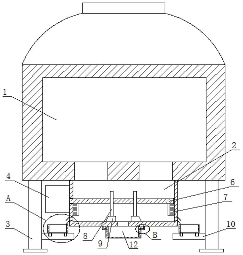
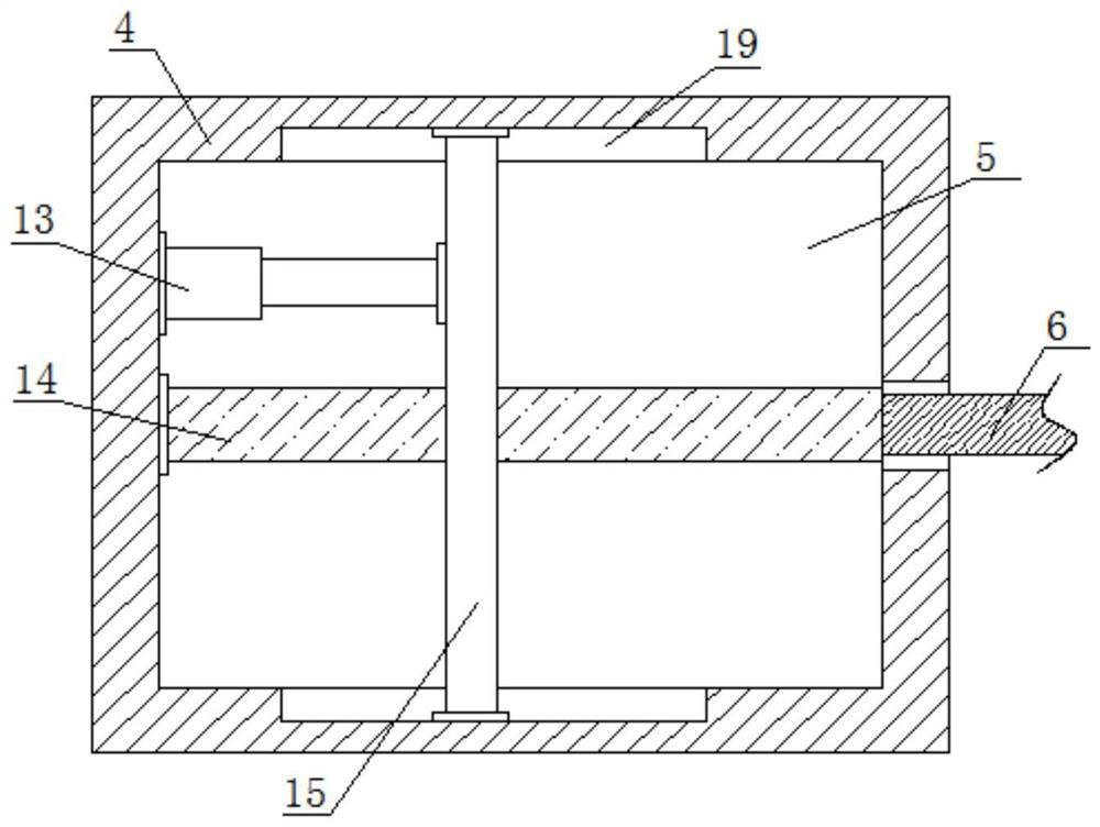
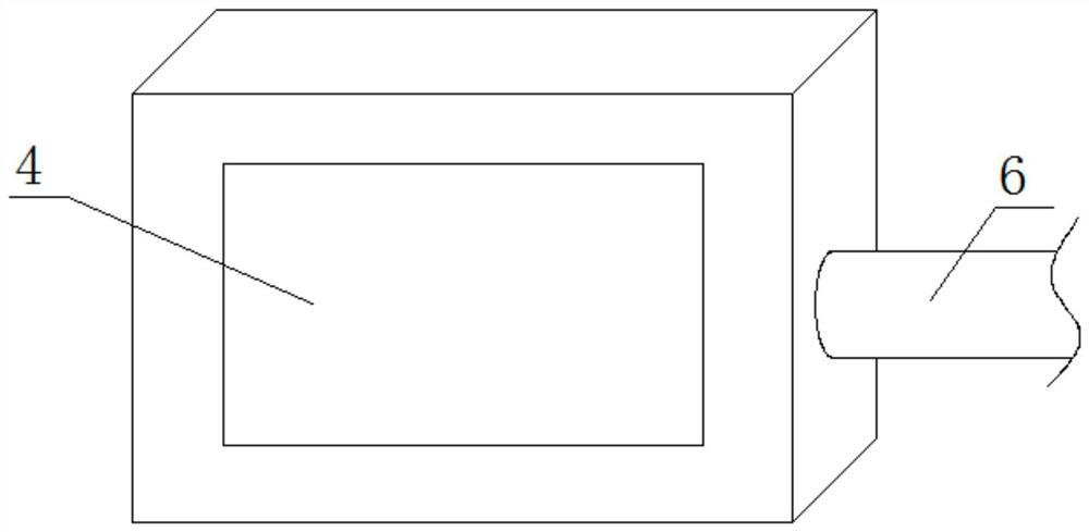
[0038] refer to Figure 1-5, a rotary hearth furnace water seal tank slagging structure, comprising a rotary hearth furnace main body 1, the bottom of the rotary hearth furnace main body 1 is provided with a water seal tank main body 2, and the bottom of the rotary hearth furnace main body 1 is symmetrically provided with two water seal The tank main body 2 is connected with a through hole, the bottom of the rotary hearth furnace main body 1 is symmetrically fixedly connected with two legs 3, one side of the water seal tank main body 2 is fixedly connected with a fixed seat 4, and a fixed chamber is arranged on the fixed seat 4 5. There is a power assembly on the fixed chamber 5, and a rotating shaft 6 is connected to the power assembly. One end of the rotating shaft 6 extends into the main body 2 of the water seal tank and is rotationally connected with one side of the inner wall of the main body 2 of the water seal tank. On the rotating shaft 6 Two cleaning brushes 7 are sym...

Embodiment 2

[0040] In the present invention, the power assembly includes an electric telescopic rod 13 fixedly connected to the inner wall of one side of the fixed chamber 5 and a ball screw 14 rotatably connected to the inner wall of one side of the fixed chamber 5. The ball screw 14 is threadedly connected with Lead screw nut 15, one end of the electric telescopic rod 13 is fixedly connected with one side of the lead screw nut 15, the other end of the rotating shaft 6 extends into the fixed chamber 5 and is fixedly connected with one end of the ball screw 14, the electric telescopic rod 13, The screw nut 15 can be moved back and forth, and the ball screw 14 can drive the rotating shaft 6 to rotate back and forth, so as to provide power for the rotating shaft 6 .

[0041] In the present invention, both sides of the main body 2 of the water seal tank 2 are symmetrically fixedly connected with two limiting plates 18, and the slag discharge port is located between the two limiting plates 18,...


PUM


Abstract

The invention belongs to the field of deslagging of rotary hearth furnaces, particularly relates to a deslagging structure and a deslagging method for a water seal tank of a rotary hearth furnace, andaims to solve the problem that effective control of hearth reducing atmosphere and hearth pressure of the rotary hearth furnace is directly affected if slag charge often exists in the water seal tankof an existing coal-based direct reduction ironmaking rotary hearth furnace and are not discharged in time, and the effective running of the rotary hearth furnace cannot be achieved. According to thescheme, the deslagging structure comprises a rotary hearth furnace body, wherein a water seal tank body is arranged at the bottom of the rotary hearth furnace body. According to the deslagging structure, the structure is reasonable, the operation is easy, a rotating shaft can rotate in a reciprocating mode through an electric telescopic rod, and the slag charge on the inner walls of the two sidesof the water seal tank body is removed through two cleaning brushes, so that the deslagging is more thorough; meanwhile, the slag charge can be pushed into a first collecting tank and a second collecting tank through deslagging plates to be collected, so that the slag charge in the water seal tank body can be discharged in time, the deslagging is thorough, and the operation of the rotary hearth furnace body is not influenced.

Description

technical field [0001] The invention relates to the technical field of slagging of a rotary hearth furnace, in particular to a slagging structure and a slagging method of a water seal tank of a rotary hearth furnace. Background technique [0002] At present, there are different rotary hearth furnace equipment in metallurgy, chemical industry and other fields, and there are strict requirements on their continuity, metering, high temperature resistance and sealing. [0003] The patent with the notification number CN111637431A discloses a waste heat boiler for recovering flue gas heat from a rotary hearth furnace. A number of second slag tube bundles for countercurrent heat exchange with gas, and superheaters, evaporators, and economizers arranged along the flue gas movement direction in the main body. By setting up two-stage slag tube bundles, multi-stage superheaters, and combined ash cleaning structures, etc., the ash accumulation and corrosion of waste heat boilers can be ...

Claims


Application Information

Patent Timeline
IPC IPC(8): F27B13/06F27D3/15
CPCF27B13/06F27D3/1545
Inventor 毛一标许晓璐王平
Owner SHAGANG GROUP
Learn More