Non-glue tail sealing device for roll

A reel and plastic sealing technology, which is applied in the field of production and processing equipment for rolled materials, can solve problems such as low efficiency, inability to form a seal at the end of the reel, and affecting the effect of the seal.

Active Publication Date: 2017-04-26
FOSHAN NANHAI DECHANGYU PAPER MASCH MFG CO LTD
View PDF8 Cites 5 Cited by
  • Summary
  • Abstract
  • Description
  • Claims
  • Application Information

AI Technical Summary

Problems solved by technology

The existing reel will be sealed with glue at the end after winding to maintain the stability of the reel. The sealing method with glue has the following three disadvantages: First, the reel must be glued before use. The process of tearing the tail will destroy the outer ring of the reel that is bonded to the tail end, so that part of the tail end cannot be used normally; second, because the glue has a certain permeability, it tends to stick to the inner paper in some cases. The user needs to tear off multiple layers before using it, which not only wastes materials, but also is inconvenient to operate; thirdly, a large amount of glue is used in the existing reel end sealing, which not only needs to increase additional material costs, but also glue is a It is a kind of chemical synthetic material, which has certain harmful components and is volatile. It will have a negative impact on the health of workers or users, whether in the production process or in use, and the use of a large amount of glue is not conducive to environmental protection.
However, the applicant only discloses its processing method in this patent, and does not disclose the specific equipme

Method used


Image

  • Non-glue tail sealing device for roll
  • Non-glue tail sealing device for roll
  • Non-glue tail sealing device for roll

Examples


Embodiment 1

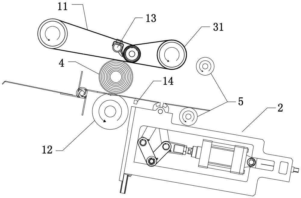
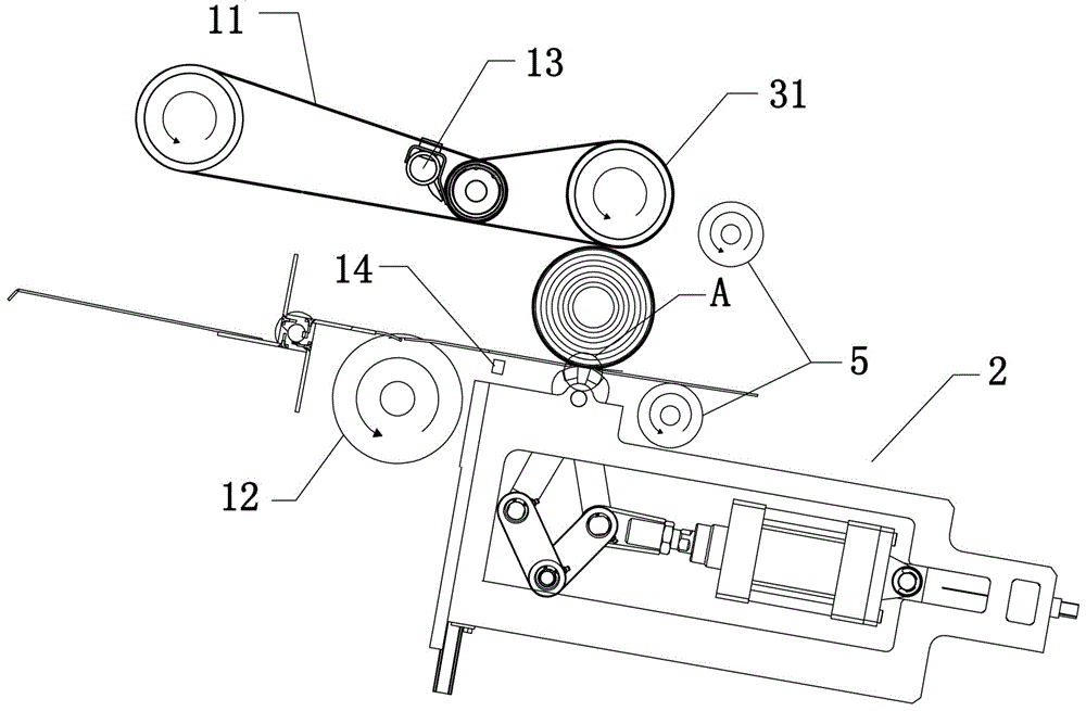
[0051] See attached figure 1 As shown, the reel glueless tail sealing device in this embodiment includes a tail-seeking mechanism for finding the tail end of the reel 4, a tail-sealing mechanism 2 located downstream of the paper-finding mechanism, and a tail-sealing mechanism 2 opposite to the tail-sealing mechanism 2 up and down. Squeezing device and finishing mechanism located downstream of tail sealing mechanism 2.

[0052] In this embodiment, the winding tail mechanism includes a conveying belt 11 , rollers 12 , air blowing pipe 13 and a detection head 14 . Wherein the conveyor belt 11 and the roller 12 are relatively up and down and rotate in the same direction, thereby forming a reel autorotation station that makes the reel 4 rotate in situ between the conveyor belt 11 and the roller 12. The very small speed difference rotates in the same direction, so that the linear speed of the reel 4 in the two rotation directions is basically the same, so that the reel 4 rotates al...

Embodiment 2

[0068] see Figure 19 As shown, the difference between the adhesive-free roll end sealing device in this embodiment and the first embodiment is that in this embodiment, the first clamping die 21a and the second clamping die 21b of the end sealing clip are arranged oppositely, and the driving unit 23 It is a telescopic cylinder and is respectively connected to push the first clamping mold 21a and the second clamping mold 21b on both sides, and the telescopic cylinders on both sides are synchronously stretched to drive the first clamping mold 21a and the second clamping mold 21b to open and close synchronously; in this implementation In the example, the extruding device includes a pressing plate 32 directly above the openings of the first clamping die 21a and the second clamping die 21b and an extruding cylinder 33 connected to the pressing plate 32 for driving the pressing plate 32 to press down. 4 for extrusion.

[0069] The working mode of the reel glueless tail sealing devi...

Embodiment 3

[0076] See attached Figure 27 As shown, the difference between the roll glue-free tail sealing device in this embodiment and Embodiment 1 is that in this embodiment, the first clamping mold 21a and the second clamping mold 21b are arranged oppositely, and the drive units 23 are located on both sides respectively. The first clamping mold 21a and the second clamping mold 21b are connected and pushed, and the two drive units 23 are synchronously expanded and contracted to drive the first clamping mold 21a and the second clamping mold 21b to open and close synchronously.


PUM


Abstract

The invention discloses a non-glue tail sealing device for a roll. The non-glue tail sealing device comprises tail sealing mechanisms and extrusion devices, and the tail sealing mechanisms and the extrusion devices are opposite in an up-down mode. The multiple sets of tail sealing mechanisms are axially arranged along the roll. Each set of tail sealing mechanism comprises a first clamping die, a second clamping die and a driving unit. Each driving unit drives the corresponding first clamping die and the corresponding second clamping die to move oppositely so that the first clamping die and the second clamping die can be opened and closed to each other. Each extrusion device is used for extruding the roll between an opening of the corresponding first clamping die and an opening of the corresponding second clamping die, so that a clamping nozzle of the first clamping die and a clamping nozzle of the second clamping die are embedded into the outer circumferential surface of the roll, and a pressing part is formed on the outer circumferential surface of the roll by closing the first clamping die and the second clamping die.

Description

technical field [0001] The present invention relates to the production and processing equipment of roll materials, more specifically to the technical field of production and processing equipment of toilet paper rolls, and in particular to a roll-roll glueless tail sealing device. Background technique [0002] The reel is a roll-shaped material formed by winding the web-shaped material, and the common forms are toilet paper rolls, plastic rolls, etc. Taking the toilet paper roll as an example, in order to maintain the stability of the roll during packaging, transportation, etc., the existing roll needs to be sealed at the tail end of the roll so that it will not fall apart. The existing reel will be sealed with glue at the end after winding to maintain the stability of the reel. The sealing method with glue has the following three disadvantages: First, the reel must be glued before use. The process of tearing the tail will destroy the outer ring of the reel that is bonded to...

Claims


Application Information

Patent Timeline
IPC IPC(8): B65H19/29
CPCB65H19/29B65H2301/41445
Inventor 陆德昌
Owner FOSHAN NANHAI DECHANGYU PAPER MASCH MFG CO LTD
Why Eureka
Try Eureka