Buried ballastless track structure

A ballastless track, buried technology, used in tracks, roads, buildings, etc., can solve the problem of not being able to completely block the accumulation of wind and sand, and achieve the effect of stable and reliable placement, avoiding the accumulation of wind and sand, and avoiding displacement.

Active Publication Date: 2017-04-26
天长市西达克家居有限公司
View PDF6 Cites 3 Cited by
  • Summary
  • Abstract
  • Description
  • Claims
  • Application Information

AI Technical Summary

Problems solved by technology

[0004] In order to solve this problem, a new solution has been introduced in the prior art, by placing the ballast bed and the track slab in the same plane, thereby overcoming the defect that wind and sand accumulate in the drop area between the track slab and the ballast bed. However, this method cannot Completely block the accumulation of wind and sand, for example, if placed on both sides of the sleeper above the track slab, a large amount of wind and sand will still accumulate

Method used


Image

  • Buried ballastless track structure
  • Buried ballastless track structure
  • Buried ballastless track structure

Examples


Embodiment 1

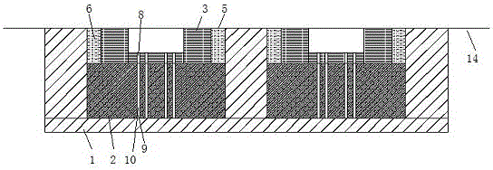
[0029] refer to figure 1 as well as Figure 8 as shown, figure 1 A schematic cross-sectional view of a buried ballastless track structure provided by the present invention, Figure 8 It is a schematic diagram of the track bed structure provided by the present invention. This embodiment provides a buried ballastless track structure, including a ballast bed 1, a track slab 2, and a sleeper 3, the sleeper 3 is erected on the track slab 2, and the ballast bed 1 has a concave pit 4. Both the track plate 2 and the sleeper 3 are arranged inside the pit 4, and the top surface of the sleeper 3 and the top surface of the ballast bed 1 are arranged on the same plane; The track bed 1 is seamlessly connected to form a whole, and the two sides of the sleeper 3 and the middle of the track bed 1 form a buffer zone 5, and shock-absorbing cotton 6 is filled in the buffer zone 5.

[0030] Wherein, there are two dimples 4 in the ballast bed 1, and two track plates 2 and sleepers 3 placed in t...

Embodiment 2

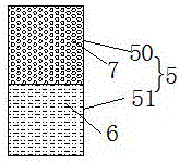
[0034] refer to figure 2 as shown, figure 2 The structure diagram of the first buffer belt provided by the present invention, specifically, this embodiment is basically the same as that of Embodiment 1, the difference is that in this embodiment, the buffer belt 5 is composed of the first buffer belt 50 and the second buffer belt 50. The buffer zone 51 is formed, the second buffer zone 51 is filled with the shock-absorbing cotton 6 , and the first buffer zone 50 is formed by pouring elastic concrete 7 . The installation direction of the first buffer belt 50 and the second buffer belt 51 is that the first buffer belt 50 is arranged on the upper side of the second buffer belt 51, and the buffer belt 5 is divided into an upper half and a lower half. That is, the upper half of the buffer belt 5 is a first buffer belt 50 poured with elastic concrete 7, and the lower half is a second buffer belt 51 filled with shock-absorbing cotton 6. The elastic concrete The top surface of the ...

Embodiment 3

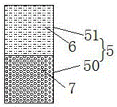
[0036] refer to image 3 as shown, image 3 The structure diagram of the second buffer belt provided by the present invention, specifically, this embodiment is basically the same as the first embodiment, the difference is that in this embodiment, the buffer belt 5 is composed of the first buffer belt 50 and the second buffer belt 50. The buffer zone 51 is formed, the second buffer zone 51 is filled with the shock-absorbing cotton 6 , and the first buffer zone 50 is formed by pouring elastic concrete 7 . The setting direction of the first buffer strip 50 and the second buffer strip 51 is that the first buffer strip 50 is arranged on the lower side of the second buffer strip 51, and the buffer strip 5 is divided into an upper half and a lower half. That is, the lower half of the buffer belt 5 is the first buffer belt 50 formed by pouring elastic concrete 7, and the upper half is the second buffer belt 51 filled with shock-absorbing cotton 6. The shock-absorbing The top surface...


PUM


Abstract

A buried ballastless track structure comprises a track bed, track boards and sleepers, wherein each sleeper is erected on the corresponding track board; the track bed is provided with downward concave pits; the track boards and the sleepers are arranged inside the pits; the top faces of the sleepers and the top face of the track bed are arranged on the same plane; the two sides of each track board are in seamless connection with the track bed to form an integral whole; buffer belts are arranged between the two sides of each track sleeper and the track bed; and the buffer belts are filled with shock absorption cotton. Wind-blown sand is prevented from accumulating in either the fall area between the track boards and the track bed or the fall areas between the track boards and the sleepers.

Description

technical field [0001] The invention relates to the technical field of railway tracks, in particular to a buried ballastless track structure. Background technique [0002] Railway lines passing through wind-sand lines, such as the unique phenomenon of railway traffic lines in Northwest China, especially in Gansu, Xinjiang and southern Xinjiang, are seriously affected by wind and sand every year, which brings a series of diseases to the infrastructure of railway lines, which are mainly divided into subgrade blowing There are two types of erosion and line sand accumulation: when the wind force reaches the sandy wind and acts on the roadbed, the sand vegetation is blown away by the wind, resulting in wind erosion of the roadbed, and the sand flow formed during the wind erosion process continuously hits the ground surface and continues to raise sand particles , into the moving air flow, so that the wind erosion process gradually expands; on the other hand, the subgrade itself is...

Claims


Application Information

Patent Timeline
Patent Type & Authority Applications(China)
IPC IPC(8): E01B2/00E01B19/00
CPCE01B2/00E01B19/00
Inventor 吴静
Owner 天长市西达克家居有限公司
Why Eureka
Try Eureka