Mounting method of stayed cable of cable-stayed bridge

An installation method and technology of cable-stayed cables, applied to cable-stayed bridges, bridges, bridge parts, etc., can solve the problems of prolonging the construction period of hanging cables, wasting construction time, increasing construction difficulty, etc., and reducing the number of times of wear , Save construction time and reduce the effect of construction procedures

Inactive Publication Date: 2017-04-26
ROAD & BRIDGE SOUTH CHINA EINGINEERING CO LTD +1
View PDF6 Cites 23 Cited by
  • Summary
  • Abstract
  • Description
  • Claims
  • Application Information

AI Technical Summary

Problems solved by technology

[0006] In the above construction method, the steel wire rope used to pull the steel strand up to the nozzle of the tower end during the construction process needs to be lowered to the bridge deck again after pulling a steel strand to pull the next steel strand Construction, on the one hand, this method wastes construction time and prolongs the construction period of the hanging rope. On the other hand, in the process of lowering the steel wire rope, the steel wire rope will also cause additional wear on the inner wall of the outer sheath tube, which is not conducive to the outer sheath tube. Protection
In addition, when the length of the steel strand reaches a certain level, the self-weight is relatively large. Compared with the vertical lifting method, the traction force required for lifting along the ascending path with an inclined angle is also greater, which increases the difficulty of construction.

Method used


Image

  • Mounting method of stayed cable of cable-stayed bridge
  • Mounting method of stayed cable of cable-stayed bridge
  • Mounting method of stayed cable of cable-stayed bridge

Examples


Embodiment Construction

[0053] The present invention is further described below with reference to the accompanying drawings and exemplary embodiments, wherein like numerals in the drawings refer to like parts throughout. Also, if a detailed description of known art is not necessary to illustrate the features of the present invention, it will be omitted.

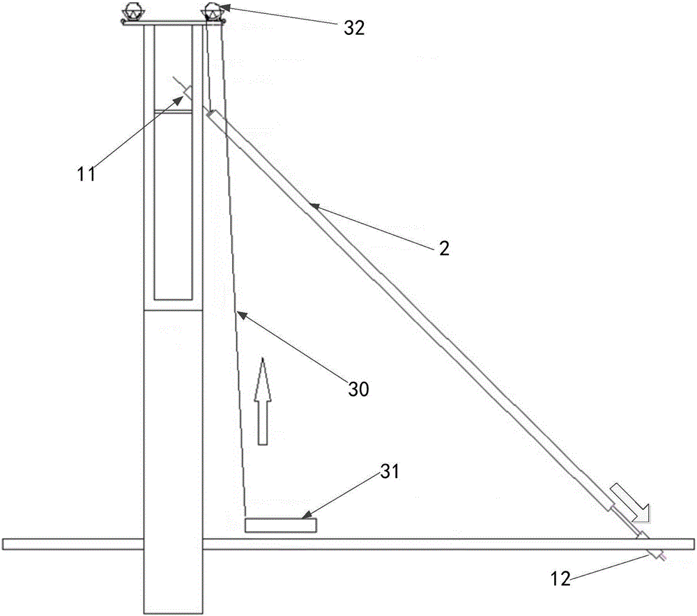
[0054] The cable-stayed cable installation schematic diagram of the cable-stayed cable installation method of the cable-stayed bridge disclosed in the present invention is as follows: figure 1 , the specific method is to install the lower beam anchoring device 12 on the main beam segment; install the tower end anchoring device 11 on the cable tower; lift the outer sheath tube 2 of the stay cable and arrange it at a preset angle to match the The anchoring device 12 under the beam and the anchoring device 11 at the tower end corresponding to the stay cables are arranged in line; Both ends of the cable are anchored and the stay cable is tensioned.

...


PUM


Abstract

The invention discloses a mounting method of a stayed cable of a cable-stayed bridge. The mounting method comprises the following steps that an under-girder anchoring device is mounted on a main girder section; a tower-end anchoring device is mounted on a cable bent tower; a stayed cable outer protection sleeve is hoisted and lifted and laid with a preset angle, and the stayed cable outer protection sleeve is collinearly arranged with the under-girder anchoring device and the tower end anchoring device which are relative to the stayed cable anchor; steel stranded wires penetrate through the outer protection sleeve one by one from the tower end to the beam end, and the two ends of each steel stranded wire are anchored on the under-girder anchoring device and the tower end anchoring device correspondingly; and the stayed cable is integrally tensioned. According to the explosive-removing unmanned aerial vehicle, the steel stranded wires penetrate through the outer protection sleeve from top to bottom, so that in the hoisting process of the steel stranded wires, the needed tractive force is reduced, construction procedures are reduced, construction time is saved, and meanwhile, abrasion to the outer protection sleeve is reduced.

Description

[0001] 【Technical field】 [0002] The invention relates to the field of bridge construction, and particularly designs a cable-stayed cable installation method for a cable-stayed bridge [0003] 【Background technique】 [0004] A cable-stayed bridge is a kind of bridge in which the main beam is directly pulled on the tower cable by many cables. It can be regarded as a multi-span elastic supporting continuous beam with stay cables instead of buttresses. It can reduce the bending moment in the beam body, reduce the building height, reduce the structural weight and save materials. The cable-stayed bridge is mainly composed of pylons, main beams and stay cables. It is a self-anchored system, and its horizontal force is borne by the beams. In addition to being supported on the pier, the beam is also supported on the stay cables drawn from the tower. According to the different materials used in the beam, it can be divided into steel cable-stayed bridge, combined beam cable-stayed br...

Claims


Application Information

Patent Timeline
Patent Type & Authority Applications(China)
IPC IPC(8): E01D21/00E01D11/04E01D19/14E01D101/30
CPCE01D11/04E01D19/14E01D21/00E01D2101/30
Inventor 刘怀刚高世强安邦庄值政孙战赢张凤凰费永忠肖向荣赵升辉檀兴华张铮葛纪平
Owner ROAD & BRIDGE SOUTH CHINA EINGINEERING CO LTD
Why Eureka
Try Eureka