
Water drainage system for water-enriched edge slope

A drainage system and water-rich technology, applied in soil drainage, application, construction, etc., can solve problems such as easy blockage, water loss, and blockage of drainage holes, and achieve the effects of improving drainage efficiency, fast water flow rate, and small hydraulic gradient

Active Publication Date: 2017-04-26
ZHEJIANG UNIV
View PDF4 Cites 4 Cited by
  • Summary
  • Abstract
  • Description
  • Claims
  • Application Information

AI Technical Summary

Problems solved by technology

Among the methods commonly used for slope drainage, the construction and excavation of drainage blind ditch is relatively difficult; horizontal drainage holes require a long drilling length, a large amount of engineering, and are easy to block; gravity drainage holes are used for drainage, but this method is often affected by drainage. The problem of hole clogging
In addition, because the water level of the reservoir and the sea water changes frequently, when the water level of the reservoir rises or the sea tide rises, the water level in front of the wall is higher than the groundwater level of the slope, and the water will seep back into the slope through the weep hole of the wall, which not only causes Water loss and a threat to the stability of slopes and retaining walls

Method used


Image

  • Water drainage system for water-enriched edge slope
  • Water drainage system for water-enriched edge slope
  • Water drainage system for water-enriched edge slope

Examples


Embodiment Construction

[0020] Below in conjunction with specific embodiment, further illustrate the present invention. It should be understood that these examples are only used to illustrate the present invention and are not intended to limit the scope of the present invention. In addition, it should be understood that after reading the teachings of the present invention, those skilled in the art can make various changes or modifications to the present invention, and these equivalent forms also fall within the scope defined by the appended claims of the present application.

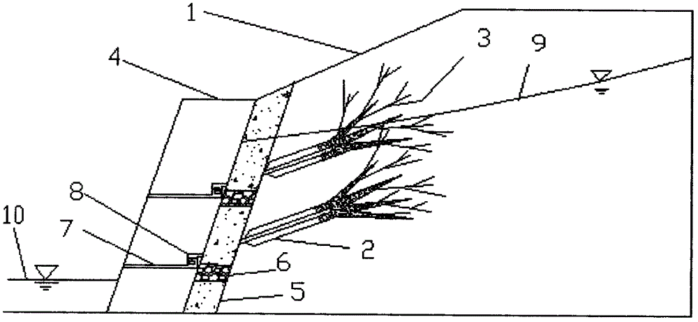
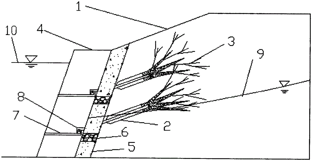
[0021] like Figure 1-7 As shown, a drainage system for water-rich slopes is composed of a water collection system and a drainage system. The water collection system is composed of a hollow anchor rod 2 and a porous concrete 3; the drainage system is composed of a gravel filter layer 5 and an aquifer 6. The control valve 8 is composed of the water collection system. Firstly, the hollow anchor rod 2 is driven into the hollow an...


PUM

PropertyMeasurementUnit
Particle sizeaaaaaaaaaa
Permeability coefficientaaaaaaaaaa
Compressive strengthaaaaaaaaaa

Abstract

The invention discloses a water drainage system for a water-enriched edge slope. The water drainage system consists of a water collection system and a water drainage system, wherein the water collection system consists of hollow anchor rods, porous concrete and grout pipes; the water drainage system consists of a gravel reversed filter layer, a water isolation layer and a control valve; directed pipe heads are arranged at the front ends of the hollow anchor rods; grout plugs and the grout pipes are arranged in the hollow anchor rods; outer sleeve heads are arranged at the rear ends of the hollow anchor rods; and the porous concrete is pressed into the soil edge slope and is dispersed along a thin area of the soil to form a root-type network. By simulation of the ecological slope protection principle, the water drainage system has anchoring and reinforcing effects and facilitates stabilization of the edge slope; the control valve is arranged between the gravel reversed filter layer and a soil retaining wall, so that water loss and a threat to the stability of the edge slope due to reverse osmosis of water into the edge slope caused by changes of the water level in front of the wall are effectively avoided, and the problem that seawater with high salinity affects the water quality of underground water of the edge slope is solved; and furthermore, under a condition that the underground water level of the edge slope is relatively high, upper and lower water discharging holes simultaneously work to improve the water drainage efficiency.

Description

technical field [0001] The invention belongs to the field of hydraulic engineering, in particular to a drainage system for water-rich slopes. Background technique [0002] In the field of hydraulic engineering, in order to ensure the stability of reservoir banks or coastal slopes, retaining walls are often set up. In the design of the retaining wall, in order to prevent the accumulation of water in the fill behind the retaining wall from forming hydrostatic pressure, the retaining wall should be equipped with drainage facilities. In the field of slope management, for water-rich slopes, after the groundwater level of the slope rises, it is necessary to quickly discharge the water from the slope. Among the methods commonly used for slope drainage, the construction and excavation of drainage blind ditch is relatively difficult; the horizontal drainage hole requires a long drilling length, the amount of work is large, and it is easy to block; the gravity drainage hole is used f...

Claims


Application Information

Patent Timeline
IPC IPC(8): E02B11/00
CPCE02B11/00
Inventor 范雲鹤孙红月于洋
Owner ZHEJIANG UNIV
Learn More