Engine waste gas cycle purifying and silencing system

An exhaust gas circulation and engine technology, which is applied to engine components, combustion engines, machines/engines, etc., can solve the problems of short service life of the system and poor exhaust gas purification effect, and achieve a simple structure, improved noise reduction effect, and convenient operation. Effect

Active Publication Date: 2017-04-26
三河市科达科技有限公司
View PDF13 Cites 3 Cited by
  • Summary
  • Abstract
  • Description
  • Claims
  • Application Information

AI Technical Summary

Problems solved by technology

[0004] In order to solve the problems of poor exhaust gas purification effect and short service life of the existing internal combustion engine exhaust gas purification and silencing system, the present invention provides an engine exhaust gas circulation purification and silencing system. The specific scheme is as follows:

Method used


Image

  • Engine waste gas cycle purifying and silencing system
  • Engine waste gas cycle purifying and silencing system
  • Engine waste gas cycle purifying and silencing system

Examples


Embodiment 1

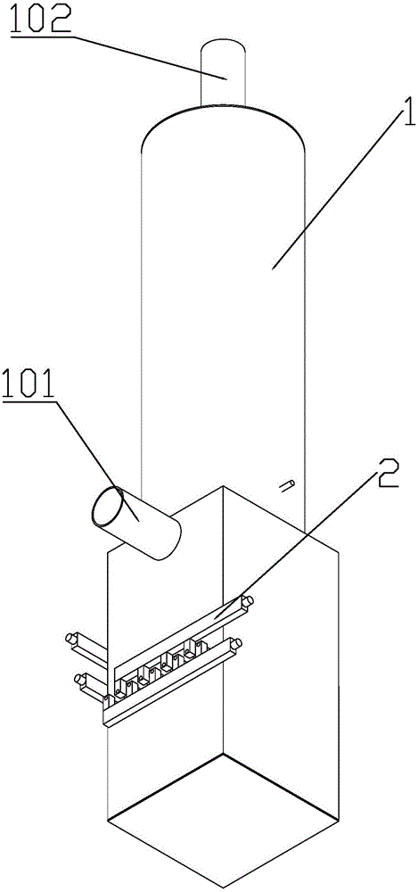
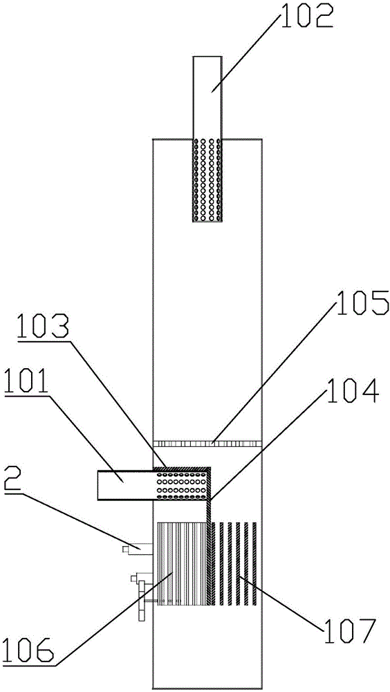
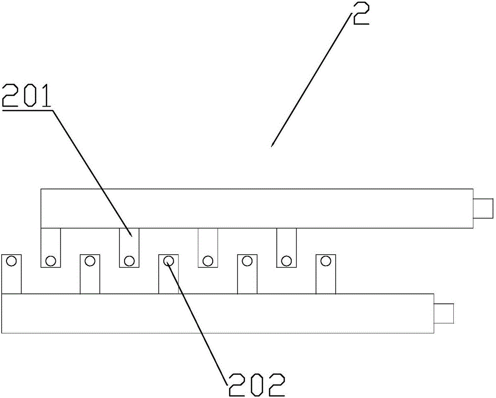
[0027] see figure 1 and figure 2 As shown, the present invention provides an engine exhaust gas circulation purification and muffler system, comprising a body 1 formed with a cavity inside and placed vertically, the side wall of the body 1 is provided with an air inlet communicating with the cavity, and the air inlet The air intake pipe 101 is connected at the top of the body 1, and the top of the body 1 is provided with an exhaust port communicating with the cavity. Two partitions 104; the first partition 103 is arranged horizontally above the air inlet, and the length of the first partition 103 is less than the inner diameter of the cavity; the second partition 104 is vertically arranged and connected with the end of the first partition 103 , the length of the second partition 104 is smaller than the distance between the first partition 103 and the bottom of the cavity. The second dividing plate 104 is provided with several vertically arranged electrode plates 106 between...

Embodiment 2

[0032] see Figure 8 to Figure 9 As shown, the difference between Embodiment 2 and Embodiment 1 is that the inner wall of the cavity is located between the discharge electrode and the bottom of the exhaust pipe, and several baffles are provided. The baffles are divided into a through-hole area and a closed area, and the through-hole area The area of ​​the baffle is 2 / 3 of the area of ​​the baffle, and several through holes are opened in the through hole area. The closed area on the baffle adjacent to the discharge electrode corresponds to the position of the dust collecting plate, and the positions of the closed areas on two adjacent baffles are staggered from each other.

[0033] Since the exhaust gas passes through the staggered baffles in the closed area before being discharged, there are overlapping parts in the through hole area, so that the exhaust gas passing through the small hole does not directly change the direction and is discharged from the exhaust pipe, which gre...


PUM


Abstract

The invention discloses an engine waste gas cycle purifying and silencing system. The engine waste gas cycle purifying and silencing system comprises a body which is internally provided with a cavity and vertically placed. An air inlet pipe is arranged on the side wall of the body. An exhaust pipe is arranged on the top of the body. A first partition plate and a second partition plate are connected to the inner wall of the cavity. The first partition plate is located above an air inlet and arranged horizontally. The second partition plate is connected to the tail end of the first partition plate and arranged vertically. A plurality of vertically arranged electrode plates are arranged between the side, close to the air inlet, of the second partition plate and the inner wall of the cavity. A plurality of vertically arranged dust collection plates are arranged between the side, away from the air inlet, of the second partition plate and the inner wall of the cavity. The inner wall of the cavity is provided with a horizontally arranged discharge electrode, and the discharge electrode is located above the first partition plate. An electrostatic generator is arranged outside the body and connected with the electrode plates, the dust collection plates and the discharge electrode. The engine waste gas cycle purifying and silencing system is simple in structure and convenient to operate, and the dust removal and purification effects are greatly improved while the silencing effect is ensured.

Description

technical field [0001] The invention relates to an exhaust gas treatment device for an internal combustion engine, in particular to an engine exhaust gas circulation muffler system. Background technique [0002] An internal combustion engine is a kind of power machinery, which is a heat engine that directly converts the heat energy released by burning fuel inside the machine into power. Internal combustion engines in a broad sense include not only reciprocating piston internal combustion engines, rotary piston engines and free piston engines, but also rotary impeller gas turbines, jet engines, etc., but internal combustion engines generally refer to piston internal combustion engines. Piston type internal combustion engine is the most common with reciprocating piston type. The piston-type internal combustion engine mixes fuel and air and burns it in its cylinder, and the heat energy released makes the cylinder generate high-temperature and high-pressure gas. The expansion ...

Claims


Application Information

Patent Timeline
Patent Type & Authority Applications(China)
IPC IPC(8): F01N3/01F01N3/08
CPCF01N1/082F01N1/083F01N3/01Y02T10/12
Inventor 王明哲苏继龙
Owner 三河市科达科技有限公司
Why Eureka
Try Eureka