Bypass type electronic controlled injector with hydraulic feedback function

An electronically controlled fuel injection and fuel injector technology, which is applied in the direction of machines/engines, fuel injection devices, engine components, etc., can solve the problems of fuel injector static pressure difference, fuel leakage, etc., to improve pressure fluctuations and increase seating speed , the effect of reducing the formation of nitrogen oxides

Active Publication Date: 2017-04-26
HARBIN ENG UNIV
View PDF8 Cites 0 Cited by
  • Summary
  • Abstract
  • Description
  • Claims
  • Application Information

AI Technical Summary

Problems solved by technology

In addition, the presence of the control plunger causes a static pressure difference in the injector, resulting in static fuel leakage

Method used


Image

  • Bypass type electronic controlled injector with hydraulic feedback function
  • Bypass type electronic controlled injector with hydraulic feedback function
  • Bypass type electronic controlled injector with hydraulic feedback function

Examples


Embodiment Construction

[0020] The present invention is described in more detail below in conjunction with accompanying drawing example:

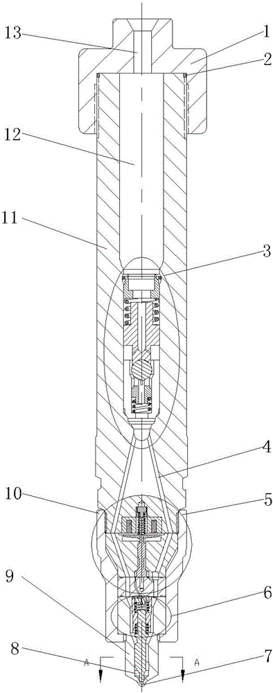
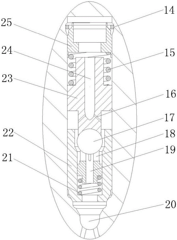
[0021] combine Figure 1-5 , The present invention includes injector head 1, restrictor valve assembly 3, solenoid valve assembly 5, needle valve assembly 6, nozzle 9, tight cap 10, injector body 11. The fuel injector head 1 is mounted on the fuel injector body 11 through threaded fitting connection, and is sealed by the sealing ring 2 placed on the fuel injector body 11 . A main oil inlet hole 13 is arranged in the injector head 1 and communicates with the pressure accumulator chamber 12 in the injector body 11 . A restrictor valve assembly 3 is arranged below the accumulator chamber 12 . The flow limiting valve assembly 3 is installed inside the fuel injector body 11, and its main structure includes a retaining ring 14, a damping spring 15, a ball valve 17, a support control slider 18, a ball valve return spring 21, a ball valve return spring seat 22, and a fl...


PUM


Abstract

The invention aims to provide a bypass type electronic controlled injector with a hydraulic feedback function. The bypass type electronic controlled injector comprises an injector head, an injector body, a flow-limiting valve assembly, a solenoid valve assembly, a needle valve assembly and other components. A pressure storage cavity is arranged in the injector body and communicates with a main oil inlet hole and the flow-limiting valve assembly, and the stability of the oil injection processes of all cylinders during large pulse width oil injection can be ensured. The flow-limiting valve assembly is installed under the pressure storage cavity, and abnormal continuous oil injection is avoided. The opening speed of the a needle valve is decreased through a feedback oil line existing in the solenoid valve assembly, so that system pressure buildup is quick, the seating speed of the needle valve is increased, and the injector can be controlled to quickly stop oil injection. A control slide block is arranged in a control cavity and makes contact with an intermediate block, and the effects of decreasing the oil injection rate in the initial stage of oil injection and accelerating seating response of the needle valve are achieved. The internal hydraulic pressure of a nozzle part is balanced, and no static pressure difference exists, so that the non-static-leakage function of the injector is achieved.

Description

technical field [0001] The invention relates to an engine fuel injection device, in particular to a high-pressure common rail fuel injection device. Background technique [0002] As the requirements for fuel economy and emission characteristics of the engine are getting higher and higher, the emission limitation mainly lies in two aspects of nitrogen oxides and particulate matter. In order to reduce the emission of nitrogen oxides, it is required to control the opening of the needle valve at the beginning of fuel injection, so that there is a low fuel injection rate and a gently rising fuel injection rate during the ignition delay period, which is beneficial to ensure the fuel injection process and Consistency in the shape of the fuel injection rate; at the end of the fuel injection, the closing speed of the needle valve is required to be fast, which is beneficial to the rapid pressure build-up of the system. That is to say, it can realize the characteristic curve of fuel i...

Claims


Application Information

Patent Timeline
Patent Type & Authority Applications(China)
IPC IPC(8): F02M47/02F02M61/10F02M61/18F02M63/00
CPCF02M47/027F02M61/10F02M61/1893F02M63/0017F02M63/0035F02M63/0036F02M63/007
Inventor 范立云张孝勇刘鹏马修真
Owner HARBIN ENG UNIV
Why Eureka
Try Eureka