Gas Turbine Combustor and Fuel Nozzle Manufacturing Method

a gas turbine and combustor technology, which is applied in the direction of turbines, machines/engines, light and heating apparatus, etc., can solve the problems of nothing referring to the root vibration stress of the fuel nozzle, and limit the effect, so as to achieve sufficient structure reliability, high damping performance, and high damping performance

Inactive Publication Date: 2021-09-30
MITSUBISHI HEAVY IND LTD
View PDF1 Cites 0 Cited by
  • Summary
  • Abstract
  • Description
  • Claims
  • Application Information

AI Technical Summary

Benefits of technology

[0007]As described above, it is possible to realize a complicated structure which leads to the improvement of dispersiveness of the fuel by 3D lamination. On the other hand, it is necessary to adopt a structure which would withstand the temporary increase in pressure fluctuation caused by the unstable combustion.
[0008]In general, vibration stress which generates in association with the pressure fluctuation reaches maximum on a root of the fuel nozzle. As one of methods of reducing the vibration stress, there is a method of increasing the diameter of the root of the fuel nozzle. Although this method has such an effect that a section modulus is increased owing to an increase in root diameter and thereby the vibration stress is reduced, this effect is limited to a case where there exists a spatial margin which is sufficient to increase the root diameter.
[0009]As another method, there is a method of improving the damping performance of the fuel nozzle and thereby reducing the vibration stress. This method makes it possible to reduce the vibration stress by incorporating a structure which improves the damping performance by utilizing the 3D additive manufacturing into the fuel nozzle without changing the shape of the fuel nozzle.

Problems solved by technology

Although this method has such an effect that a section modulus is increased owing to an increase in root diameter and thereby the vibration stress is reduced, this effect is limited to a case where there exists a spatial margin which is sufficient to increase the root diameter.
However, nothing is referred to the problem of the vibration stress on the root of the fuel nozzle and the improvement of the damping performance by the 3D additive manufacturing such as those described above.

Method used


Image

  • Gas Turbine Combustor and Fuel Nozzle Manufacturing Method
  • Gas Turbine Combustor and Fuel Nozzle Manufacturing Method
  • Gas Turbine Combustor and Fuel Nozzle Manufacturing Method

Examples


first embodiment

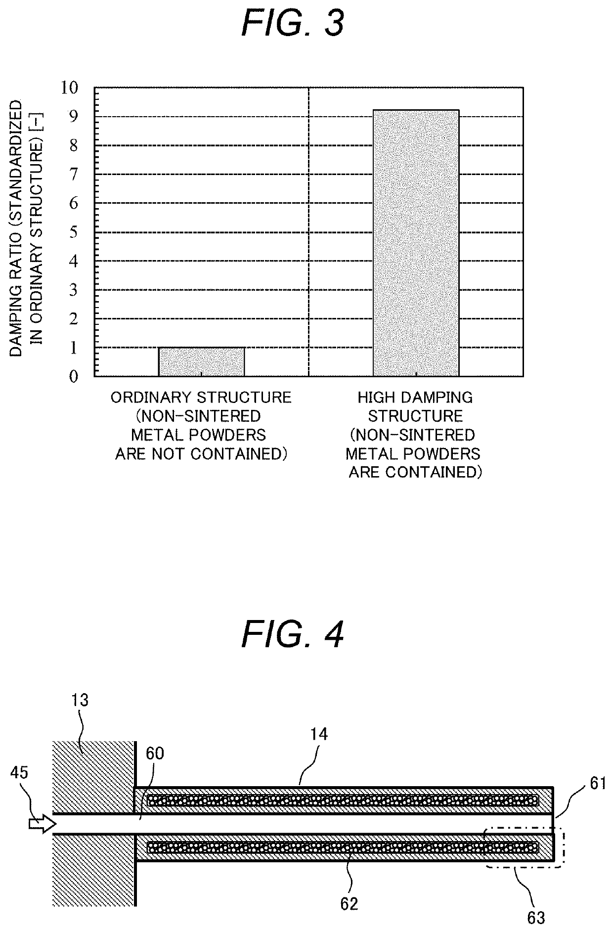
[0041]A structure and a manufacturing method of the fuel nozzle 14 according to the first embodiment of the present invention will be described with reference to FIG. 4 and FIG. 5. FIG. 4 is a sectional diagram illustrating one example of the fuel nozzle 14 of the first embodiment and is an enlarged diagram illustrating one example of a part 50 of the burner 17 which is illustrated in FIG. 2.

[0042]A fuel flow path 60 that the fuel 45 flows is formed in the center of the fuel nozzle 14. Streams of the fuel 45 which is distributed by the fuel nozzle plate 13 pass through the respective fuel nozzles 14 and are injected from leading ends 61 of the respective fuel nozzles 14.

[0043]The fuel nozzle 14 according to the first embodiment has a structure in which a region 62 on which the non-sintered metal powders are present is formed between the fuel flow path 60 and an outer circumferential face of the fuel nozzle 14. It is possible to manufacture this structure by leaving the metal powders...

second embodiment

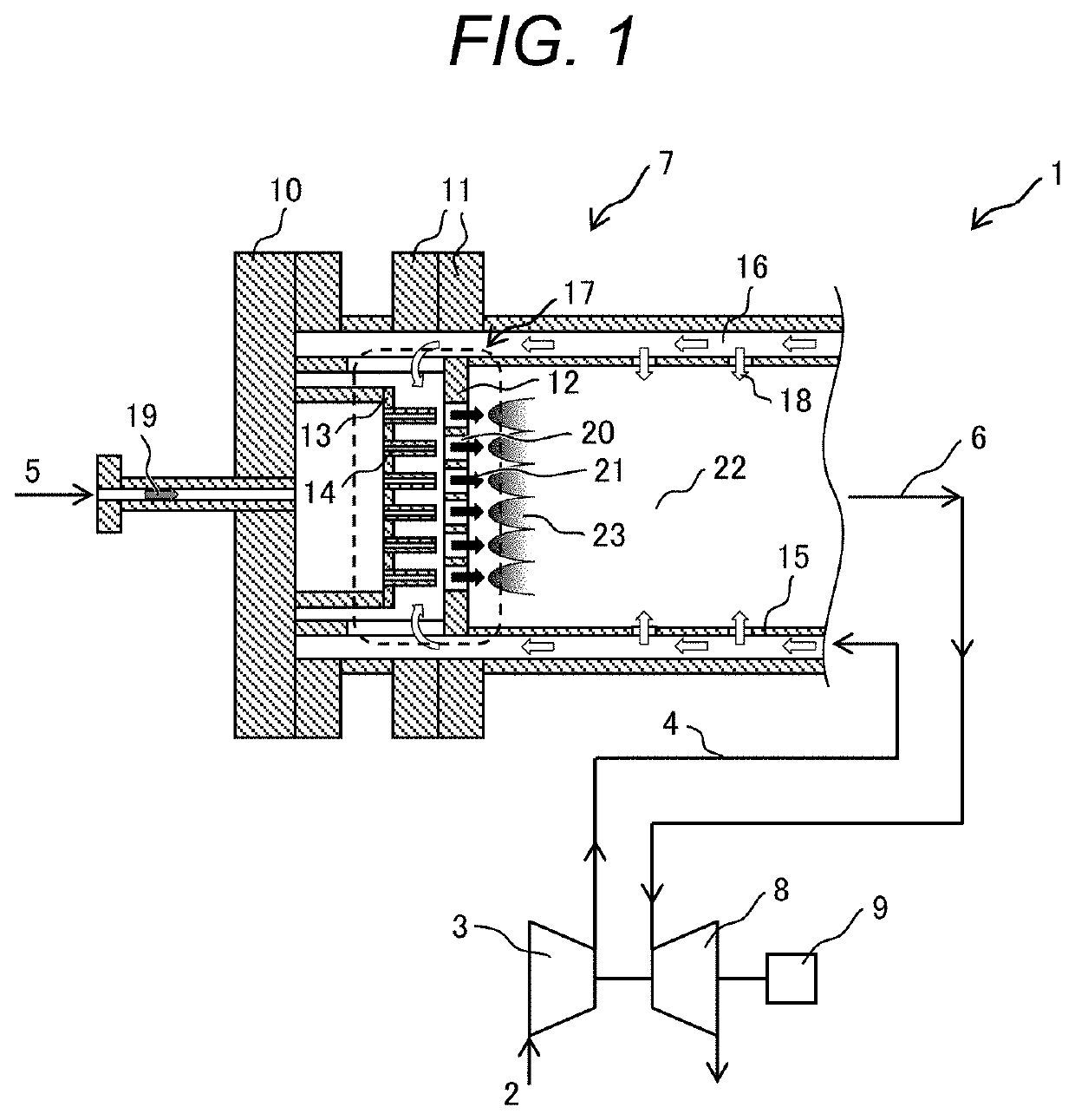
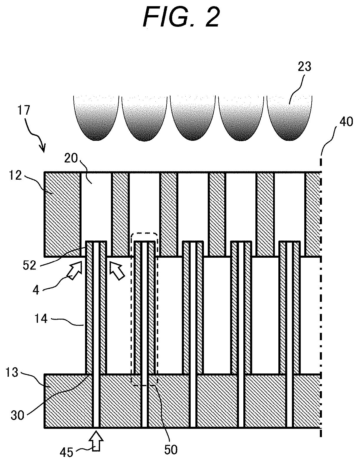
[0048]A structure and a manufacturing method of the fuel nozzle 14 according to the second embodiment of the present invention will be described with reference to FIG. 6. FIG. 6 is a sectional diagram illustrating one example of the fuel nozzle 14 according to the second embodiment and is an enlarged diagram of the part 50 of the burner 17 which is illustrated in FIG. 2.

[0049]There are cases where the material strength of the section of the fuel nozzle 14 which contains the non-sintered metal powders is reduced due to a reduction in section modulus and stress concentration. In a case where the stress on the root of the fuel nozzle 14 is high, it is necessary to separate a metal powder non-sintered region from the root.

[0050]Accordingly, in the second embodiment, it becomes possible to damp the vibration with no reduction of the strength of the root by disposing a metal powder non-sintered region 70 on a part (a region) other than the root of the fuel nozzle 14 as illustrated in FIG....

third embodiment

[0052]A structure and a manufacturing method of the fuel nozzle 14 according to the third embodiment of the present invention will be described with reference to FIG. 7. FIG. 7 is a sectional diagram illustrating one example of the fuel nozzle 14 according to the third embodiment and is an enlarged diagram of the part 50 of the burner 17 which is illustrated in FIG. 2.

[0053]In the fuel nozzle 14 which is tapered as illustrated in FIG. 7, there are cases where a space in which the metal powder non-sintered region is to be disposed is not present on the leading end side.

[0054]Accordingly, in the third embodiment, it becomes possible to leave the non-sintered metal powders even in the tapered fuel nozzle 14 and then to damp the vibration by disposing a metal powder non-sintered region 80 on the root side of the fuel nozzle 14 as illustrated in FIG. 7.

[0055]That is, the fuel nozzle 14 according to the third embodiment has the second region (the metal powder non-sintered region 80) betwe...


PUM

PropertyMeasurementUnit
temperatureaaaaaaaaaa
pressureaaaaaaaaaa
pressure fluctuationaaaaaaaaaa

Abstract

There is provided a gas turbine combustor which includes a fuel nozzle which is high in damping performance against vibration stress caused by unstable combustion, in the gas turbine combustor which includes the fuel nozzle which is molded by 3D additive manufacturing. In the gas turbine combustor which includes the fuel nozzle which is molded by the 3D additive manufacturing, the fuel nozzle has a first region on which metal powders are sintered and a second region which is surrounded by the first region and on which the metal powders are not sintered.

Description

CLAIM OF PRIORITY[0001]The present application claims priority from Japanese Patent application serial no. 2020-061684, filed on Mar. 31, 2020, the content of which is hereby incorporated by reference into this application.BACKGROUND OF THE INVENTION[0002]The present invention pertains to a structure of a gas turbine combustor and a method of manufacturing the gas turbine combustor and, in particular, relates to a technology which is effectively applied to a structure and a manufacturing method for a fuel nozzle which is manufactured by a metal 3D additive manufacturing technology.[0003]In a gas turbine, strict environmental standards are set on NOx which is exhausted in operation of the gas turbine for reducing a load that exhaust gas exerts on the environment. Since the exhaust amount of NOx is increased with the increasing temperature of flames, it is necessary to locally suppress formation of the high-temperature flames and thereby to realize uniform combustion. A complicated bu...

Claims


Application Information

Patent Timeline
Patent Type & Authority Applications(United States)
IPC IPC(8): F02C7/232F23R3/28B33Y80/00B33Y10/00B22F10/28
CPCF02C7/232F23R3/28B33Y80/00F05D2240/36B22F10/28F05D2220/32F05D2230/31B33Y10/00F23R3/42B22F5/10F23R3/286B22F5/009Y02P10/25F23R3/00
Inventor KUMAGAI, SATOSHINAGANO, KOTAOTA, ATSUO
Owner MITSUBISHI HEAVY IND LTD
Why Eureka
Try Eureka