
Non-contact electromagnetic micro pump device

A non-contact, non-contact technology, applied in the direction of pumps, liquid displacement machines, pumps with flexible working elements, etc., can solve the problems of complex manufacturing process, large volume, high cost, etc.

Active Publication Date: 2017-04-26
TECHNICAL INST OF PHYSICS & CHEMISTRY - CHINESE ACAD OF SCI
View PDF6 Cites 9 Cited by
  • Summary
  • Abstract
  • Description
  • Claims
  • Application Information

AI Technical Summary

Problems solved by technology

However, since Si and its compounds are used as chip materials, there are several limitations in microfluidic chips: First, complex processing techniques such as etching are required
The production is complicated, and the volume is large, and the integration level is not high
Secondly, because the electrode of the ordinary MHD pump is in direct contact with the driven solution, a hydrolysis reaction is prone to occur under the condition of an applied voltage, and the hydrolysis reaction can often generate bubbles. Third, the electrode material in the ordinary micro MHD pump is usually metal platinum, but platinum Electrode micromachining requires complex manufacturing process and high cost

Method used


Image

  • Non-contact electromagnetic micro pump device
  • Non-contact electromagnetic micro pump device
  • Non-contact electromagnetic micro pump device

Examples


Embodiment Construction

[0037] In order to understand the above-mentioned purpose, features and advantages of the present invention more clearly, the present invention will be further described in detail below in conjunction with the accompanying drawings and specific embodiments. It should be noted that, in the case of no conflict, the embodiments of the present application and the features in the embodiments can be combined with each other.

[0038] In the following description, many specific details are set forth in order to fully understand the present invention. However, the present invention can also be implemented in other ways different from those described here. Therefore, the protection scope of the present invention is not limited by the specific details disclosed below. EXAMPLE LIMITATIONS.

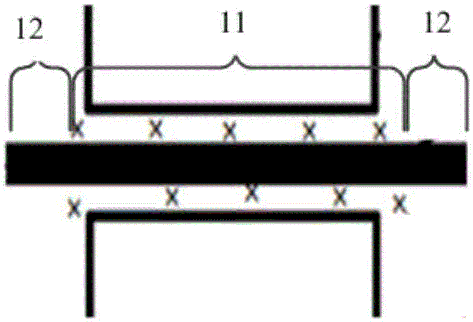
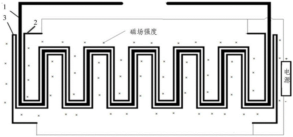
[0039] Such as Figure 1A As shown, a non-contact electromagnetic micropump device according to an embodiment of the present invention includes:

[0040] Fluid microchannel 1, wherein a solution to ...


PUM


Abstract

The invention relates to the micro flow control field, in particular to a non-contact electromagnetic micro pump device. The non-contact electromagnetic micro pump device includes: a fluid micro flow channel, wherein a solution to be driven is arranged in the fluid micro flow channel; a first electrode micro flow channel and a second electrode micro flow channel which are parallel to the fluid micro flow channel, are arranged at two sides of the fluid micro flow channel in a non-contact manner, and are connected to two ends of a power supply respectively; a first film and a second film which are arranged between the first and second electrode micro flow channels and the fluid micro flow channel respectively, and have micro conductivity; and a magnet which is used for generate a magnetic field perpendicular to a plane where the first electrode micro flow channel, the fluid micro flow channel, and the second electrode micro flow channel are located so as to allow the solution to be driven to move along the fluid micro flow channel. According to the technical scheme, the electrical field generated by the electrode micro flow channels non-contacting the solution to be driven and an external orthotropic magnetic field can generate the lorentz force to drive the solution to be driven to move along the fluid micro flow channel, and then the flow speed and the flow direction of the solution to be driven can be controlled.

Description

technical field [0001] The invention relates to the field of micro-flow control, in particular to a non-contact electromagnetic micro-pump device. Background technique [0002] Microfluidic chip or lab-on-a-chip is the integration of basic operation units such as cell culture, sorting, lysis involved in the biological field, or sample preparation, collection, reaction, separation, detection, etc. On the chip, a network of microfluidic channels is formed, and the controllable fluid runs through the entire system to realize various functions of conventional biological or chemical laboratories. [0003] Microfluidic chips have the ability to shrink a biological or chemical laboratory onto a thin sheet of only a few square centimeters, and are an important science and technology in this century. One of the important features of the microfluidic chip is to manipulate the fluid in the microchannel network. Therefore, the design of the microfluidic drive unit micropump has become ...

Claims


Application Information

Patent Timeline
IPC IPC(8): F04B43/04
Inventor 桂林刘静周旭艳
Owner TECHNICAL INST OF PHYSICS & CHEMISTRY - CHINESE ACAD OF SCI
Learn More