Backlight unit and liquid crystal module

A technology of backlight unit and light-transmitting film, applied in optics, nonlinear optics, instruments, etc., can solve the problems of uneven brightness, large thickness and size, and achieve the effect of thin and flexible design

Inactive Publication Date: 2017-04-26
WUHAN CHINA STAR OPTOELECTRONICS TECH CO LTD
View PDF6 Cites 1 Cited by
  • Summary
  • Abstract
  • Description
  • Claims
  • Application Information

AI Technical Summary

Problems solved by technology

The advantage of the bottom-mounted backlight is that the light utilization rate is high, and it is easy to realize a large area. The disadvantage is that the brightness is uneven and the thickness is large. With the increasing demand for portable devices such as notebook computers, there is an urgent need for thinner, Lightweight LCD modules, so the application of side-mounted backlights is increasing
[0003] figure 1 It is a liquid crystal module 10 composed of a side-mounted backlight in the prior art. The backlight unit includes a light guide plate 12, an LED light source 131 placed on the left side of the light guide plate 12, and the LED light source 131 is arranged on a flexible printed circuit board 133. A reflective sheet 11 is provided below the light guide plate 12, and an intermediate layer 14, an adhesive layer 16, and a liquid crystal panel 15 are sequentially provided above the light guide plate 12. figure 1 It can be seen from the figure that the backlight unit mainly includes the light guide plate 12, the LED light source 131, and the reflective sheet 11. The general thickness is about 0.7 mm, and the plastic frame 17 carries the components above the light guide plate. For flexible panels, the backlight unit in the prior art has limited the development of flexible liquid crystal modules due to its non-bendable LED light source and light guide plate. Under the impact of OLED technology, liquid crystal display screens need to be extremely thin Only with a high color gamut can it compete with OLED. Due to the limitation of brightness and assembly process, the thinnest backlight unit in the prior art can only be about 0.5mm, which cannot meet the needs of development. Therefore, in order to adapt to thinner LCD modules design and design of flexible liquid crystal modules, there is an urgent need for a new type of backlight unit

Method used


Image

  • Backlight unit and liquid crystal module
  • Backlight unit and liquid crystal module
  • Backlight unit and liquid crystal module

Examples


Embodiment Construction

[0023] The backlight unit and the liquid crystal module of the present invention will be described in more detail below with reference to the accompanying drawings. The upper, lower, left and right in the following are all relative to the position of the drawings and should not be construed as limiting the present invention.

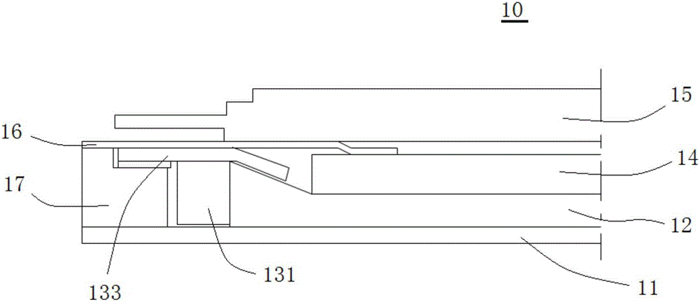
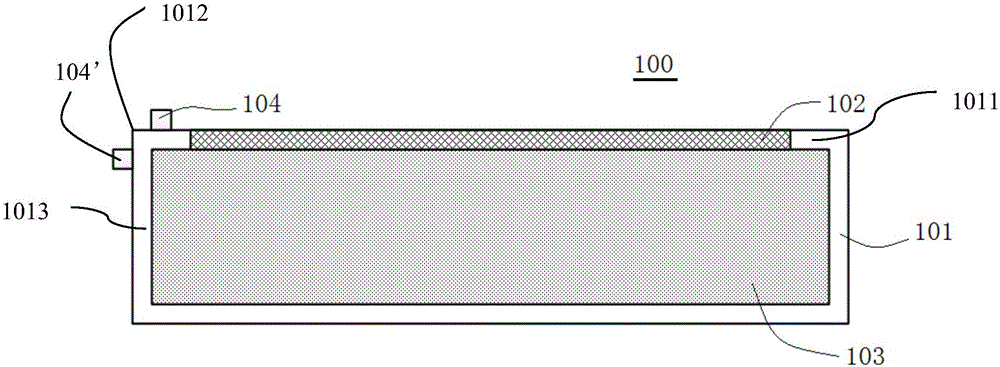
[0024] figure 2 It is a schematic diagram of the structure of the backlight unit 100 proposed by the present invention. It can be seen from the figure that the backlight unit 100 includes an opaque casing 101. The first casing wall 1011 of the casing 101 has an opening, and the light-transmitting film 102 The open part is blocked, and together with the casing 101, a sealed cavity 103 is formed inside. In order to make the sealed cavity 103 well sealed, the light-transmitting film 102 can be integrally formed with the casing 101, or the light-transmitting film 102 and the casing can be formed in other ways. The bodies 101 are combined together so that t...


PUM


Abstract

The invention relates to the technical field of liquid crystal display manufacturing and provides a backlight unit. The backlight unit comprises a light-tight shell and a light-transmitting film, wherein the shell has an opening part; the opening part is blocked by the light-transmitting film; a sealing chamber is jointly formed by the light-transmitting film and the shell in the interior; an electroluminescence matter is filled into the sealing chamber; a positive electrode and a negative electrode are arranged on an outer wall of the shell; and after the voltage is applied to the positive electrode and the negative electrode, the electroluminescence matter in the sealing chamber can emit light; the light spreads to the exterior of the shell through the light-transmitting film. The invention also provides a liquid crystal module containing the backlight unit. The backlight unit not only can supply a high-luminance and uniform light source to a liquid crystal panel but also can realize the thin and soft design of the liquid crystal module.

Description

technical field [0001] The invention relates to the technical field of liquid crystal display manufacturing, and in particular to a backlight unit and a liquid crystal module. After the liquid crystal module uses the backlight unit proposed by the invention, not only the brightness and display uniformity of the liquid crystal panel are ensured, but also the liquid crystal module is realized. The thin design of the group can also meet the design of flexible liquid crystal modules. Background technique [0002] Liquid crystal displays are different from self-luminous CRTs, PDPs, etc. Since the liquid crystal itself does not emit light, an external light source is indispensable for display. The light source located on the back of the display screen is called the backlight source. According to the positional relationship between the light source (fluorescent lamp, LED, EL, etc.) and the light guide plate, the backlight source can be divided into a bottom-mounted type and a side-...

Claims


Application Information

Patent Timeline
Patent Type & Authority Applications(China)
IPC IPC(8): G02F1/13357
CPCG02F1/133602G02F1/133614
Inventor 刘中杰顾华
Owner WUHAN CHINA STAR OPTOELECTRONICS TECH CO LTD
Why Eureka
Try Eureka