Carbon fiber composite core optical fiber wire strain clamp

A tension clamp, composite core technology, applied in the direction of optical fiber/cable installation, adjusting/maintaining mechanical tension, etc. The effect of preventing damage and ensuring signal transmission efficiency

Active Publication Date: 2017-04-26
STATE GRID HENAN ELECTRIC POWER ELECTRIC POWER SCI RES INST +1
View PDF7 Cites 1 Cited by
  • Summary
  • Abstract
  • Description
  • Claims
  • Application Information

AI Technical Summary

Problems solved by technology

The disadvantage of this structure is that: the optical fiber wire is only fastened by the pressing block, not only the problem of jumper wires, but also the fastening effect is not good
The above-mentioned patent can certainly protect the o

Method used


Image

  • Carbon fiber composite core optical fiber wire strain clamp
  • Carbon fiber composite core optical fiber wire strain clamp
  • Carbon fiber composite core optical fiber wire strain clamp

Examples


Embodiment 1

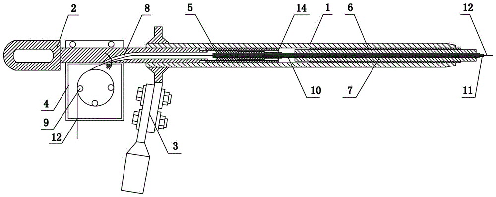
[0027] Such as figure 1 As shown, the present invention includes a cable clamp body 1, a steel anchor 2, a drainage plate 3 and an optical fiber protection box. The optical fiber protection box includes two sealed and fastened box covers 4, and the steel anchor 2 is threadedly connected to the left end of the cable clamp body 1 for drainage. The plate 3 is fixedly connected to the outer wall of the wire clamp body 1 by bolts, the wire clamp body 1 is a hollow tube, the left end of the wire clamp body 1 is fixedly connected to the wedge-shaped clamp support 14, and the matching wedge-shaped clamp 5 is installed in the wedge-shaped clamp support 14 , the right end of the clamp body 1 is equipped with an inner liner 6, and an arc-shaped through hole 8 is provided in the steel anchor 2, and the right end of one end of the arc-shaped through hole 8 is connected with the clamp body 1, and the center line of the arc-shaped through hole 8 The angle α between the tangent line of the mi...

Embodiment 2

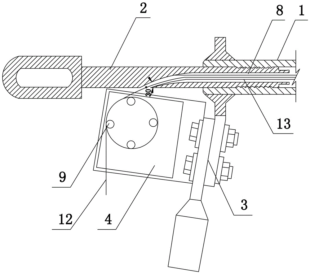
[0030] The present invention includes a cable clamp body 1, a steel anchor 2, a drainage plate 3 and an optical fiber protection box, the optical fiber protection box includes two sealed and fastened box covers 4, the steel anchor 2 is threaded to the left end of the cable clamp body 1, and the drainage plate 3 passes through the Bolts are fixedly connected to the outer wall of the wire clamp body 1, the wire clamp body 1 is a hollow tube, the left end in the wire clamp body 1 is fixedly connected to the wedge-shaped clamp support 14, and the matching wedge-shaped clamp 5 is installed in the wedge-shaped clamp support 14, and the wire clamp The right end of the main body 1 is equipped with an inner liner 6, an arc-shaped through hole 8 is provided in the steel anchor 2, and a transparent rubber tube 13 is arranged in the arc-shaped through-hole 8, and the right end of one end of the arc-shaped through hole 8 communicates with the clamp body 1. The angle α between the tangent of...

Embodiment 3

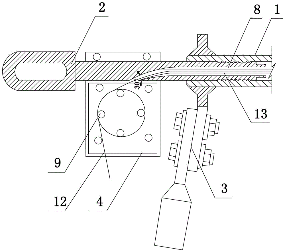
[0033]The present invention includes a cable clamp body 1, a steel anchor 2, a drainage plate 3 and an optical fiber protection box, the optical fiber protection box includes two sealed and fastened box covers 4, the steel anchor 2 is threaded to the left end of the cable clamp body 1, and the drainage plate 3 passes through the Bolts are fixedly connected to the outer wall of the wire clamp body 1, the wire clamp body 1 is a hollow tube, the left end in the wire clamp body 1 is fixedly connected to the wedge-shaped clamp support 14, and the matching wedge-shaped clamp 5 is installed in the wedge-shaped clamp support 14, and the wire clamp The right end of the main body 1 is equipped with an inner liner 6, an arc-shaped through hole 8 is provided in the steel anchor 2, and a transparent rubber tube 13 is arranged in the arc-shaped through-hole 8, and the right end of one end of the arc-shaped through hole 8 communicates with the clamp body 1. The angle α between the tangent of ...


PUM


Abstract

The invention discloses a carbon fiber composite core optical fiber wire strain clamp which comprises a wire clamp body, a steel anchor, a drainage plate fixedly connected to the outer wall of the wire clamp body, and an optical fiber protection box. The wire clamp body is a hollow tube, one end in the wire clamp body is fixedly connected to a wedge clamp support which is internally provided with a matched wedge clamp, and the other end in the wire clamp body is equipped with a liner tube. The steel anchor is arranged at one end close to the wedge clamp support and is threadingly connected to the wire clamp body, and the steel anchor is internally provided with an arc-shaped through hole. One end of the arc-shaped through hole communicates with the wire clamp body, and the optical fiber protection box is internally provided with more than two winding columns. Through arranging the arc-shaped through hole in the steel anchor, the structure can withstand wire tension and fix a wire, an optical fiber can be protected, the damage to the optical fiber due to exposure and an excessive angle is prevented, thus a line connection mode is improved, and a high performance signal transmission function is realized.

Description

technical field [0001] The invention belongs to the technical field of power transmission equipment, in particular to a carbon fiber composite core optical fiber wire tension clamp. Background technique [0002] The research on carbon fiber composite core conductors began in the 1990s and was developed by Japanese scholars. In 2004, the United States first applied carbon fiber conductors to power transmission lines. my country's research on carbon fiber conductors began in 2005, and the first application of this conductor in my country was in the expansion and transformation of 220,000 lines in Liaoning and Fujian in 2006. Carbon fiber composite core wire has the characteristics of high strength, large carrying capacity, good heat resistance, small linear expansion coefficient, light weight, and good corrosion resistance. It is an energy-saving and environmentally friendly wire, and has a wide range of applications in overhead transmission lines prospect. [0003] Carbon f...

Claims


Application Information

Patent Timeline
IPC IPC(8): H02G7/02G02B6/48
CPCG02B6/48H02G7/02
Inventor 李梦丽吕中宾张博宋高丽艾文君魏建林杨晓辉赵嘉娜庞锴刘博王超赵书杰张宇鹏
Owner STATE GRID HENAN ELECTRIC POWER ELECTRIC POWER SCI RES INST
Why Eureka
Try Eureka