
Protection device, power supply device and terminal

A technology for protection devices and power terminals, which is applied in emergency protection circuit devices, emergency protection circuit devices for limiting overcurrent/overvoltage, circuit devices, etc., and can solve problems such as terminal failure to charge, VBUS short circuit to GND, customer return, etc.

Inactive Publication Date: 2017-04-26
YULONG COMPUTER TELECOMM SCI (SHENZHEN) CO LTD
View PDF3 Cites 2 Cited by
  • Summary
  • Abstract
  • Description
  • Claims
  • Application Information

AI Technical Summary

Problems solved by technology

[0010] The technical problem mainly solved by the present invention is to provide a protection device, a power supply device and a terminal, so as to solve the problem in the prior art that when a surge or DC high voltage causes a short circuit between VBUS and GND, causing the terminal to return due to the inability to charge

Method used


Image

  • Protection device, power supply device and terminal
  • Protection device, power supply device and terminal
  • Protection device, power supply device and terminal

Examples


Embodiment 1

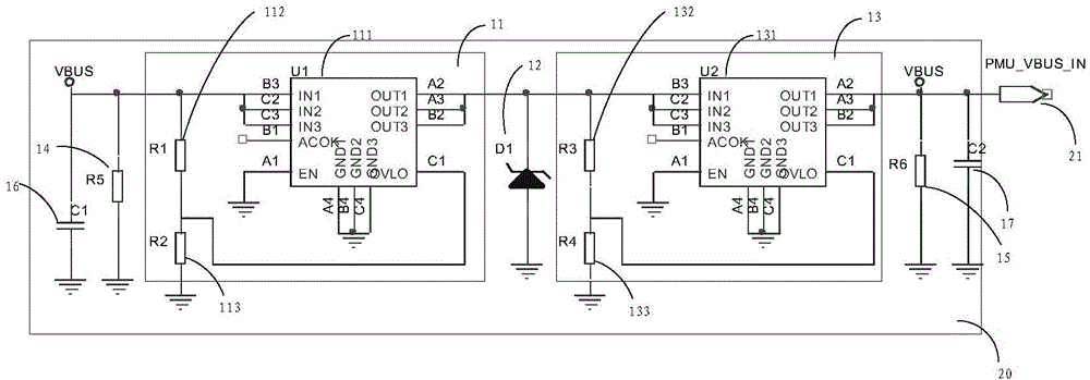
[0030] This embodiment provides a protection device, see figure 1 , figure 1 A schematic diagram of a protection device provided for this embodiment, the protection device includes: a first overvoltage protection unit 11, a surge protection unit 12 and a second overvoltage protection unit 13; the first overvoltage protection unit 11, a surge protection unit The protection unit 12, the second overvoltage protection unit 13 and the unit to be protected ( figure 1 (not shown in ) are connected in parallel between the power supply terminal VBUS and the ground terminal in sequence from near to far from the power supply terminal VBUS;

[0031] The unit to be protected includes a power management unit, that is, a PMU chip.

[0032] The first overvoltage protection unit 11 and the second overvoltage protection unit 13 are respectively used to protect the parallel connection between the power supply terminal VBUS and the ground terminal when the DC voltage of itself is equal to or gr...

Embodiment 2

[0053] This embodiment provides a power supply device, please refer to figure 2 , figure 2 A schematic diagram of a power supply device provided in this embodiment, the power supply device includes the protection device 20 in the first embodiment, and also includes a unit to be protected 21, and the unit to be protected 21 includes a power management unit, namely figure 2 The PMU chip in.

[0054] The protection device 20 includes: a first overvoltage protection unit 11, a surge protection unit 12 and a second overvoltage protection unit 13; the first overvoltage protection unit 11, a surge protection unit 12, a second overvoltage protection unit 13 and The units to be protected 21 are sequentially connected in parallel between the power supply terminal VBUS and the ground terminal in order from near to far from the power supply terminal VBUS;

[0055] The first overvoltage protection unit 11 and the second overvoltage protection unit 13 are respectively used to protect t...

Embodiment 3

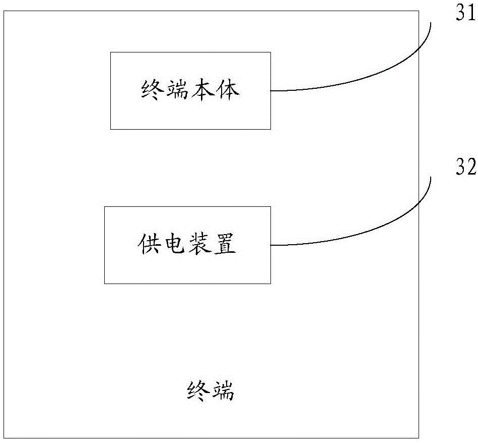
[0076] This embodiment provides a terminal, see image 3 , image 3 A schematic diagram of a terminal provided in this embodiment, the terminal includes a terminal body 31 and a power supply device 32 in the second embodiment.

[0077] The power supply device 32 includes the protection device 20 in the first embodiment, and also includes the unit to be protected 21, and the unit to be protected 21 includes a power management unit, namely figure 2 The PMU chip in.

[0078] The protection device 20 includes: a first overvoltage protection unit 11, a surge protection unit 12 and a second overvoltage protection unit 13; the first overvoltage protection unit 11, a surge protection unit 12, a second overvoltage protection unit 13 and The units to be protected 21 are sequentially connected in parallel between the power supply terminal VBUS and the ground terminal in order from near to far from the power supply terminal VBUS;

[0079]The first overvoltage protection unit 11 and th...


PUM


Abstract

The invention provides a protection device, a power supply device and a terminal. The protection device comprises a first overvoltage protection unit, a surge protection unit and a second overvoltage protection unit, wherein the first overvoltage protection unit, the surge protection unit, the second overvoltage protection unit and a to-be-protected unit are sequentially connected in parallel between a power supply end VBUS and a ground end in a from-near-to-far distance to the power supply end VBUS, the overvoltage protection unit and the second overvoltage protection unit are respectively used for protecting the unit which is connected in parallel between the power supply end VBUS and the ground end and is more distant from the power supply end VBUS compared with the corresponding overvoltage protection unit from being influenced by a DC voltage when the DC voltage loaded on the corresponding overvoltage protection unit is equal to or greater than a corresponding threshold, and the surge protection unit is used for protecting the unit which is connected in parallel between the power supply end VBUS and the ground end and is more distant from the power supply end VBUS compared with the corresponding overvoltage protection unit from being influenced by a surge when a voltage or a current loaded on the corresponding overvoltage protection unit generates the surge. The protection device is advantaged in that a surge problem on a VBUS line is solved, a DC high voltage problem on the VBUS line can be solved, a client withdrawal rate is reduced, and user experience is improved.

Description

technical field [0001] The present invention relates to the technical field of terminals, in particular to a protection device, a power supply device and a terminal. Background technique [0002] Currently, there are three mobile phone anti-surge solutions: [0003] Option 1. Connect a high-power surge tube in parallel to GND (ground terminal) on the VBUS (USB voltage) line; [0004] Option 2. Connect an OVP (Over Voltage Protection) chip in parallel to GND on the VBUS line; [0005] Option 3: Connect a high-power surge tube in parallel to GND on the VBUS line first, and then connect an OVP chip in parallel to GND after the high-power surge tube. [0006] Disadvantages of prior art: [0007] Option 1. The high-power surge tube only has a protective effect on the surge voltage or surge current of us (microsecond) level. Although the peak power is high, the average power is low. When encountering DC high voltage of ms (millisecond) level It will burn out soon, causing VBUS...

Claims


Application Information

Patent Timeline
Patent Type & Authority Applications(China)
IPC IPC(8): H02H9/04
CPCH02H9/047
Inventor 涂瑞高思
Owner YULONG COMPUTER TELECOMM SCI (SHENZHEN) CO LTD
Learn More