
A low standby power circuit architecture

A standby circuit, low standby technology, applied in the field of power electronics, to achieve the effect of reducing loss and switching sensitivity

Active Publication Date: 2019-07-12
杭州奥能电源设备有限公司
View PDF4 Cites 0 Cited by
  • Summary
  • Abstract
  • Description
  • Claims
  • Application Information

AI Technical Summary

Problems solved by technology

The traditional method of reducing standby loss is to reduce the loss details and make the power supply work in hiccup mode

Method used


Image

  • A low standby power circuit architecture
  • A low standby power circuit architecture

Examples


Embodiment 1

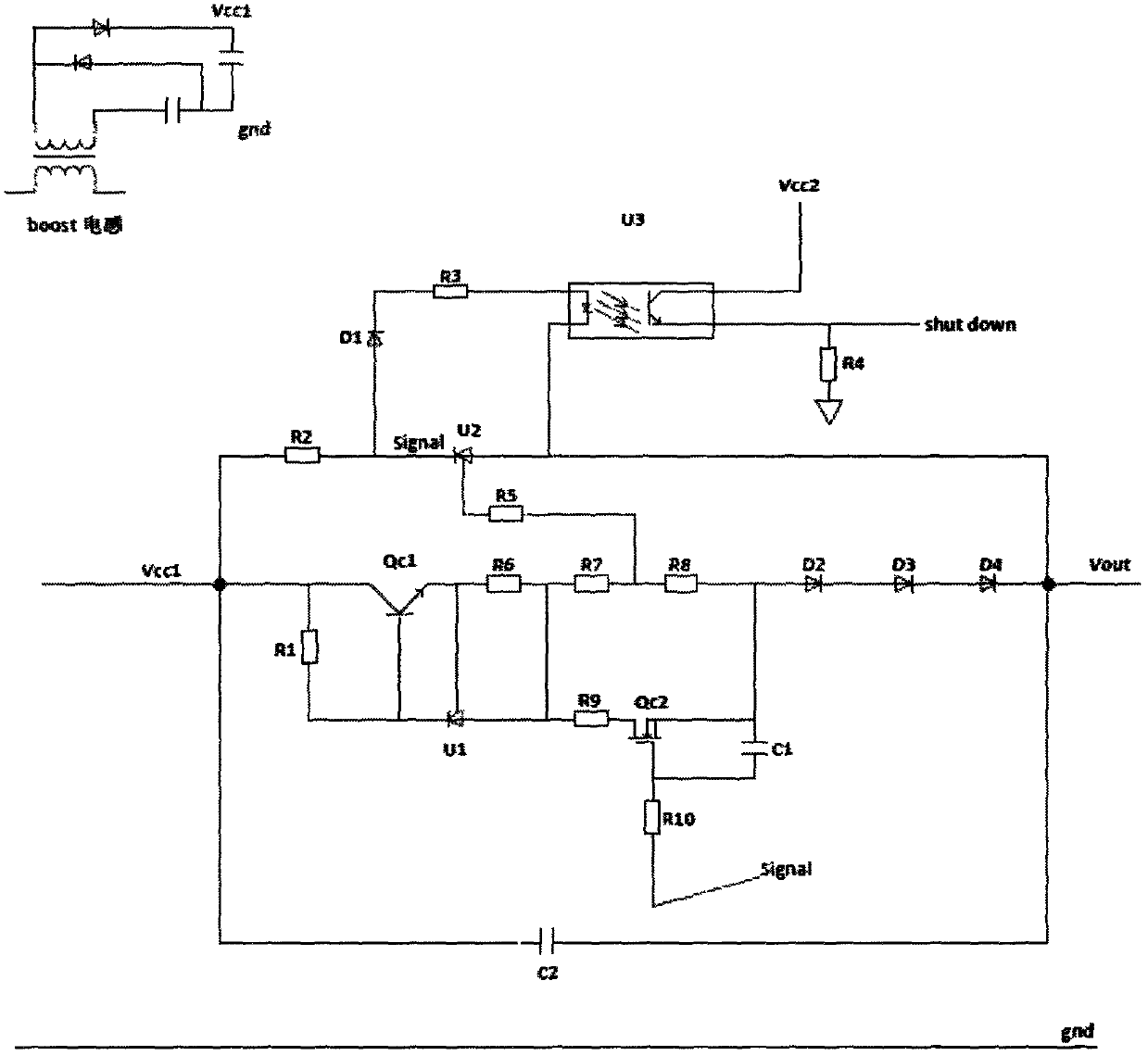
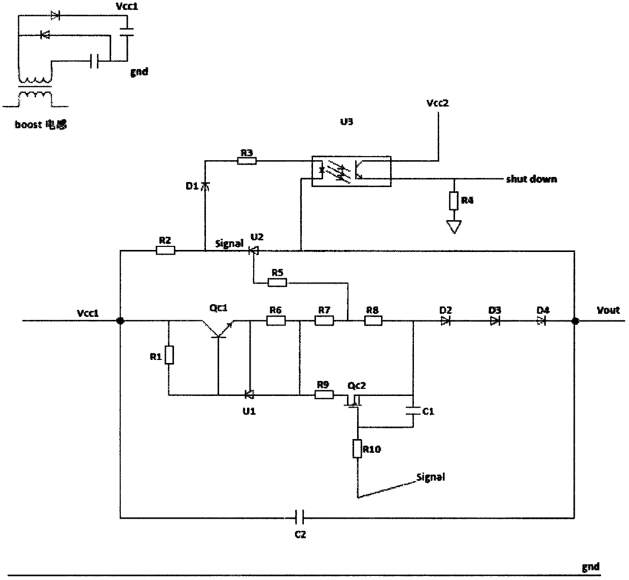
[0014] A low standby power consumption circuit architecture, including an auxiliary power circuit and a standby circuit, the standby circuit is connected in series between the load and the auxiliary power circuit, the standby circuit includes a photocoupling unit and a control unit; the control unit includes a three-terminal regulator U2, The anode of the three-terminal voltage regulator U2 is connected to the output terminal of the standby circuit, and the cathode is connected to the input terminal of the standby circuit through a resistor; the photoelectric coupling unit is connected in parallel on both sides of the three-terminal voltage regulator U2, and the three-terminal voltage regulator U2 controls the pass through of the photoelectric coupling unit. The photoelectric coupling unit outputs the current signal shutdown; the cathode of the three-terminal regulator U2 outputs a voltage signal signal; the control unit also includes an insulated gate type field effect transist...


PUM


Abstract

The present invention relates to the field of power electronics technology, in particular to a low standby power consumption circuit architecture, including an auxiliary power circuit and a standby circuit, the standby circuit is connected in series between the load and the auxiliary power circuit, and the standby circuit includes a photoelectric coupling unit and a control unit; The control unit includes a three-terminal regulator U2, the anode of the three-terminal regulator U2 is connected to the output terminal of the standby circuit, the cathode is connected to the input terminal of the standby circuit through a resistor, and the reference terminal is connected to the output terminal of the standby circuit through a resistor and a diode; photoelectric coupling The units are connected in parallel on both sides of the three-terminal voltage regulator U2, the three-terminal voltage regulator U2 controls the on-off of the photoelectric coupling unit, the photoelectric coupling circuit outputs a current signal shutdown; the cathode of the three-terminal voltage regulator U2 outputs a voltage signal signal. It has remarkable technical effects: the circuit branch switching is more sensitive, can effectively reduce loss, and the standby power can be reduced to 200mw.

Description

technical field [0001] The invention relates to the technical field of power electronics, in particular to the design of a low standby power consumption circuit architecture. Background technique [0002] As life and office become more and more intelligent, more and more small power supplies consume electricity, and the total consumption accounts for an astonishingly large proportion of electricity consumption. However, many devices have low utilization rates and are always in a standby state, and the standby loss appears to be higher than normal. The efficiency when using is more prominent. To this end, North America launched the 80PLUS standard and promoted it to the world. How to reduce standby loss is a core task of every power supply manufacturer. The traditional method to reduce standby loss is to reduce the loss details and make the power supply work in hiccup mode. Low-power power supplies (less than 100 watts) barely meet the 0.5-watt standby loss index. If you ...

Claims


Application Information

Patent Timeline
Patent Type & Authority Patents(China)
IPC IPC(8): H02M1/00
CPCH02M1/00H02M1/0032Y02B70/10
Inventor 张峰
Owner 杭州奥能电源设备有限公司
Learn More