Pressure compensated subsea electrical system

A pressure compensation, electrical system technology, applied in electrical components, transformer/inductor cooling, electrical equipment structural components, etc., can solve problems such as increasing the cost and weight of pressure compensation underwater electrical systems

Active Publication Date: 2017-04-26
ABB (SCHWEIZ) AG
View PDF8 Cites 3 Cited by
  • Summary
  • Abstract
  • Description
  • Claims
  • Application Information

AI Technical Summary

Problems solved by technology

This surface can be extended by using tank corrugations, cooling fins or external heat exc

Method used


Image

  • Pressure compensated subsea electrical system
  • Pressure compensated subsea electrical system
  • Pressure compensated subsea electrical system

Examples


Example Embodiment

[0027] The invention will now be described more fully hereinafter with reference to the accompanying drawings, in which certain embodiments of the invention are shown. However, the present invention can be implemented in many different forms and should not be construed as being limited to the embodiments set forth herein; on the contrary, these embodiments are provided as examples so that this disclosure will be thorough and complete, and will Those skilled in the art fully convey the scope of the invention. Throughout the description, the same numbers refer to the same elements.

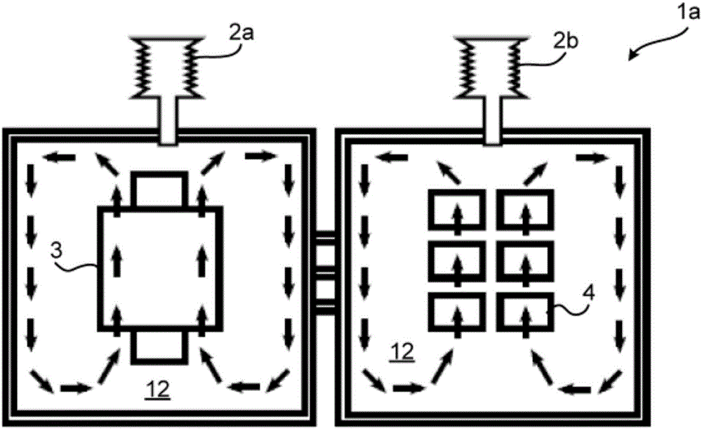
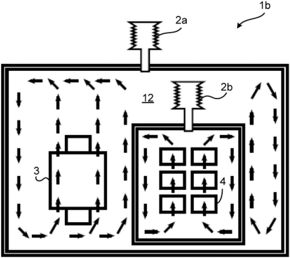
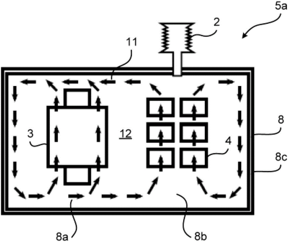
[0028] Cooling systems for electrical equipment, especially for underwater electrical systems, are used to cool electrical components, such as transformers, power converters, power electronic building blocks, semiconductor modules, connectors, and capacitor units. These electrical components generate heat that needs to be dissipated by the cooling system. The cooling system of the underwater electric...


PUM


Abstract

There is presented a pressure compensated subsea electrical system (5a, 5b, c, 5d, 5e). The pressure compensated subsea electrical system comprises a housing (8) filled with a dielectric liquid (12). The housing has a first housing portion (8a) and a second housing portion (8b) in pressure communication with each other. The first housing portion comprises a transformer (3), and the second housing portion comprises apower converter (4). The pressure compensated subsea electrical system comprises a pressure compensator (2) arranged to compensate pressure inside the housing. The pressure compensator is enabled to compensate pressure in both the first housing portion and the second housing portion.

Description

technical field [0001] The present invention relates to subsea electrical systems, and in particular to pressure compensated subsea electrical systems. Background technique [0002] In general, underwater electrical installations and equipment usually require high standards regarding durability, long-term functionality and independence during operation. Subsea electrical installations that need to be cooled during operation, such as subsea converters, require autonomous and permanent cooling of their components. It is known to use low compressibility dielectric liquids, such as mineral oil, as cooling fluids. The dielectric fluid can also consist of natural or synthetic esters. In general, dielectric fluids are used to provide a pressure compensating environment and also serve as an electrical insulation medium for electrical components placed in electrical installations, such as capacitor units. Therefore, the tanks of power electronic subsea equipment, such as subsea co...

Claims


Application Information

Patent Timeline
IPC IPC(8): H05K5/06H01F27/14
CPCH01F27/14H05K5/068H05K7/20236H05K7/20927H02M7/068F28D1/022H05K7/209
Inventor T·拉内里德T·格拉丁格H·伦登曼E·维尔塔南T·瓦格纳T·科伊维鲁奥马
Owner ABB (SCHWEIZ) AG
Why Eureka
Try Eureka