
System for enlarging cogeneration centralized heat supply scale

A technology for central heating and cogeneration, applied in hot water central heating systems, heating systems, heating fuels, etc., can solve problems such as prominent conflicts in distribution of interests, difficulty in determining heat prices, and inability to set up peak-shaving heat sources, etc. Achieve the effect of fully exerting heating capacity, improving heating efficiency, and solving the conflict of interest distribution

Inactive Publication Date: 2017-05-03
DALIAN BAOGUANG ENERGY SAVING AIR CONDITIONING EQUIP
View PDF10 Cites 22 Cited by
  • Summary
  • Abstract
  • Description
  • Claims
  • Application Information

AI Technical Summary

Problems solved by technology

[0004] Aiming at the bottleneck problems such as the inability to set up peak-shaving heat sources, prominent profit distribution contradictions, and difficulty in determining heat prices in the transformation of combined heat and power central heating, the present invention provides a system for expanding the scale of combined heat and power centralized heating

Method used


Image

  • System for enlarging cogeneration centralized heat supply scale

Examples


Embodiment Construction

[0017] The present invention will be further explained below in combination with specific embodiments.

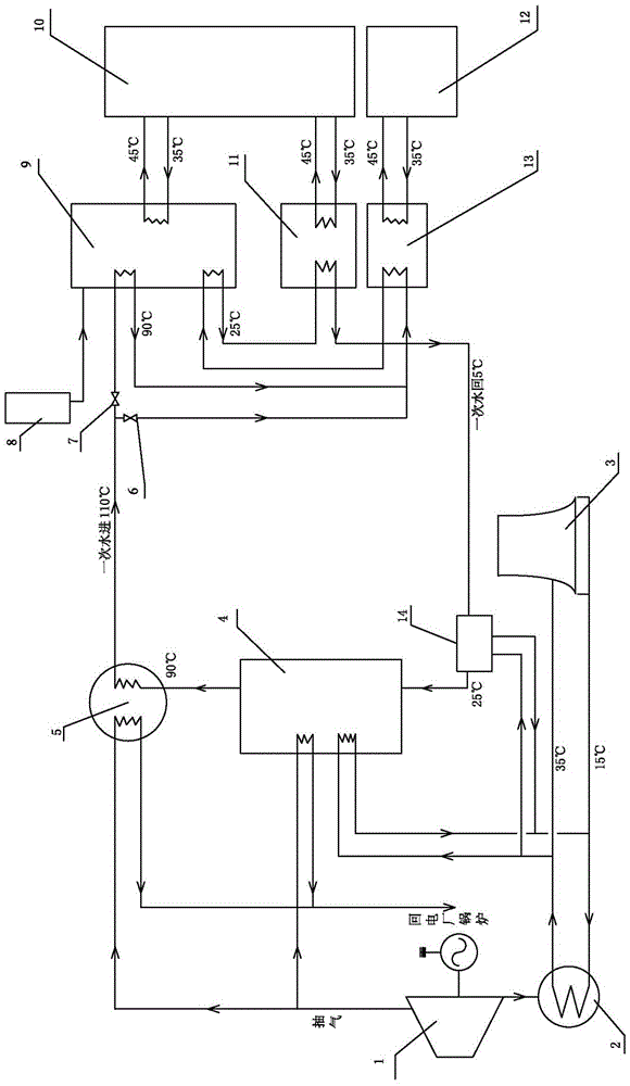
[0018] Such as figure 1 As shown in the figure, a system for enlarging the scale of centralized heat supply for combined heat and power generation, the high-temperature primary heating network water supply from the steam-water heat exchanger 5 of the thermal power plant is divided into two paths, and one path enters the multi-heat source-driven absorption heat pump 9 as a driving heat source , after releasing heat and cooling down, it enters the heat exchanger A13 to exchange heat with the secondary heat network of the original user 12; the other one directly enters the heat exchanger A13 to exchange heat with the secondary heat network of the original user 12; the two-way heat network water supply pipe The control valve A6 and the control valve B7 are respectively set on the road. After heat exchange and cooling from the heat exchanger A13, the return water of the primary ...


PUM


Abstract

The invention discloses a system for enlarging a cogeneration centralized heat supply scale. High-temperature primary heat supply network supply water discharged from a steam-water heat exchanger of a heat and power plant is divided into two paths, one path of high-temperature primary heat supply network supply water enters a multi-heat-source driven absorption heat pump so as to be used as a driving heat source and enters a heat exchanger A after being cooled by releasing heat to exchange heat with a secondary heat supply network of an original user; the other path of high-temperature primary heat supply network supply water directly enters the heat exchanger A to exchange heat with the secondary heat supply network of the original user; primary heat supply network return water sequentially enters the multi-heat-source driven absorption heat pump and an electrically-driven heat pump through pipelines after being cooled by heat exchange realized by the heat exchanger A so as to be used as a low-temperature heat source and enters the primary heat supply network supply water again after being heated step by step; and hot water discharged from the multi-heat-source driven absorption heat pump and the electrically-driven heat pump is used for supplying heat to new users through the secondary heat supply network. Two paths of high-temperature primary heat supply network water supply pipelines are respectively provided with control valves A and B for regulating the quantity of the high-temperature primary heat supply network supply water entering the multi-heat-source driven absorption heat pump and the heat exchanger A, so that the efficient operation of cogeneration centralized heat supply is realized.

Description

technical field [0001] The invention relates to a heat supply system, in particular to a system for improving energy utilization efficiency and enlarging the centralized heat supply scale of combined heat and power generation. Background technique [0002] At present, although combined heat and power generation has realized the step-by-step utilization of energy, it still belongs to the traditional heating method, with low heating efficiency and large energy waste. Today's conventional heating methods generally adopt a primary heating network supply water temperature of 110°C and a primary heating network return water temperature of 70°C. The temperature difference between the supply and return water is small, resulting in high energy consumption of the circulating pump, low transmission efficiency, and serious heat loss in the supply and return water pipeline. Since the return water temperature of the primary heating network is 70°C, the waste heat from the cooling tower of...

Claims


Application Information

Patent Timeline
IPC IPC(8): F24D3/18F24D19/10
CPCY02B30/12Y02P80/15F24D3/18F24D19/1015F24D2200/32
Inventor 毕海洋刘盛木姚伟君
Owner DALIAN BAOGUANG ENERGY SAVING AIR CONDITIONING EQUIP
Learn More