Display device

A display device and display panel technology, applied in static indicators, nonlinear optics, instruments, etc., can solve problems affecting signal integrity, display unevenness, voltage output errors, etc., to improve display unevenness and reduce signal disturbances Effect

Inactive Publication Date: 2017-05-03
AU OPTRONICS CORP
View PDF5 Cites 2 Cited by
  • Summary
  • Abstract
  • Description
  • Claims
  • Application Information

AI Technical Summary

Problems solved by technology

The crosstalk phenomenon causes voltage output errors, and the parasitic effects generated by it seriously affect the integrity of the signal, causing the liquid crystal to receive wrong display information, resulting in uneven display (such as V-line mura), and affecting the display screen of the liquid crystal display quality

Method used


Image

  • Display device
  • Display device
  • Display device

Examples


Embodiment Construction

[0044] Below in conjunction with accompanying drawing, structural principle and working principle of the present invention are specifically described:

[0045] The detailed features and advantages of the present invention are described in detail below in the embodiments, the content of which is sufficient for those skilled in the art to understand the technical content of the present invention and implement it accordingly. The related objects and advantages of the present invention can be easily understood by anyone skilled in the art. The following examples further illustrate the concept of the present invention in detail, but do not limit the scope of the present invention in any way.

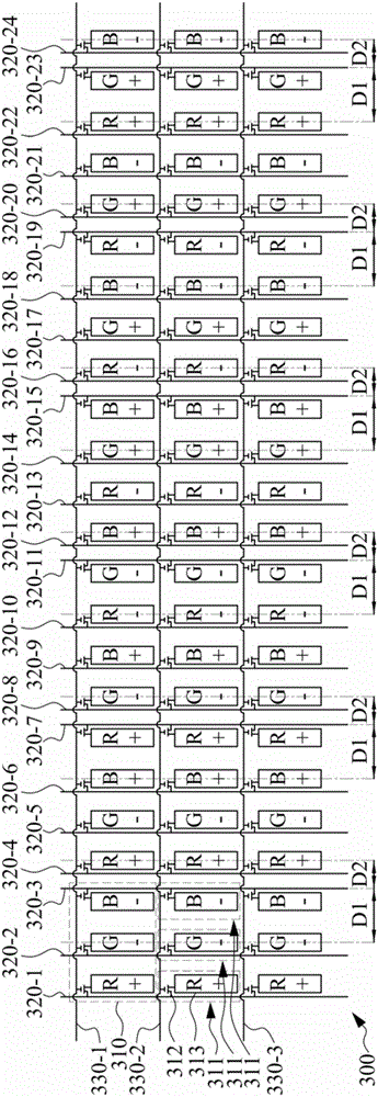
[0046] Please refer to Figure 3A as well as Figure 3B , Figure 3A and Figure 3B It is a schematic diagram of driving polarity of a display device according to the first embodiment of the present invention, specifically, Figure 3A is the polar arrangement of the pixel array in the fi...


PUM


Abstract

A display device. The display device has a display panel and a drive circuit. The display panel has a pixel array formed by a plurality of pixel electrodes. The drive circuit has a plurality of data lines to drive the pixel electrodes of the pixel array. The pixel electrode of the (N-1)th row in the pixel array of the Mth column and the data line driving the pixel electrode of the Nth row have a first distance D1, the pixel electrodes of the (N+1)th row in the pixel array of the Mth column and the data line driving the pixel electrodes of the Nth row have a second distance D2, and the first distance D1 is larger than the second distance D2.

Description

technical field [0001] The invention relates to a display device. Background technique [0002] Please refer to figure 1 , figure 1 It is a prior art display device 100 according to the present disclosure. Such as figure 1 As shown, the display device 100 in the prior art of the present disclosure mainly includes a display panel 110 , a source driver 120 and a gate driver 130 . In more detail, the display panel has a pixel array 112 composed of a plurality of pixel units P. The source driving circuit 120 provides multiple rows of data lines ( D1 ˜ Dn ), and writes the data signal into each pixel unit P of the pixel array 112 according to the setting of the timing controller 140 . In addition, the gate driving circuit 130 provides a plurality of scanning lines ( S1 ˜ Sm ), and sets the scanning signal according to the timing controller 140 to enable each pixel unit P of the pixel array 112 . In a traditional display device architecture, each pixel unit P in the pixel ar...

Claims


Application Information

Patent Timeline
Patent Type & Authority Applications(China)
IPC IPC(8): G09G3/36G02F1/1362
CPCG02F1/1362G09G3/3614
Inventor 王遵淯吴昆瑯郑美俊杨哲豪王嘉驹黄怡平
Owner AU OPTRONICS CORP
Why Eureka
Try Eureka