Traction, rolling and unrolling device of heat preservation quilt for solar-panel greenhouse

A solar panel greenhouse and thermal insulation quilt technology, which is applied in greenhouse cultivation, application, climate change adaptation, etc., can solve the problems of unfavorable thermal insulation, affecting crop growth, affecting sunlight injection, etc., and achieves the effect of good thermal insulation

Inactive Publication Date: 2017-05-10
DONGGUAN TIANHE ELECTROMECHANICAL DEV CO LTD
0 Cites 11 Cited by

AI-Extracted Technical Summary

Problems solved by technology

The existing roll-up device has the following determinations. After the insulation is rolled, it is arranged above the top of the greenhouse, thereby affecting the ...

Abstract

The invention discloses a traction, rolling and unrolling device of a heat preservation quilt for a solar-panel greenhouse. The traction, rolling and unrolling device comprises the solar-panel greenhouse, an unrolling device, a rolling device and the heat preservation quilt, wherein the top of the solar-panel greenhouse is arched; the unrolling device and the rolling device are respectively arranged on the two lateral walls of the solar-panel greenhouse; one end of the heat preservation quilt is fixedly provided with an unrolling guide rod, and the other end of the heat preservation quilt is fixedly provided with a plurality of evenly-distributed rolling ropes; the unrolling guide rod is fixedly provided with a plurality of evenly-distributed unrolling ropes; the other ends of the unrolling ropes are fixed onto the unrolling device; the other ends of the rolling ropes are fixed onto the rolling device; a pair of guide plates in front-rear symmetry are arranged on the front and rear lateral walls in the length direction of the solar-panel greenhouse; the unrolling guide rod is slidably arranged on the guide plates. By the traction, rolling and unrolling device, the heat preservation quilt is flat and smooth when being unrolled at the top of the solar-panel greenhouse, and a better heat preservation effect is achieved; when the heat preservation quilt is rolled, the heat preservation quilt is stored at the lower end of the lateral wall of the solar-panel greenhouse, and sunlight incidence is unaffected.

Application Domain

Technology Topic

Image

  • Traction, rolling and unrolling device of heat preservation quilt for solar-panel greenhouse
  • Traction, rolling and unrolling device of heat preservation quilt for solar-panel greenhouse
  • Traction, rolling and unrolling device of heat preservation quilt for solar-panel greenhouse

Examples

  • Experimental program(1)

Example Embodiment

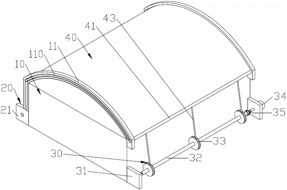
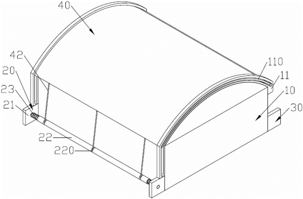
[0018] Such as figure 1 , figure 2 As shown, a heat-preserving and winding-up device for a solar panel greenhouse includes a solar panel greenhouse 10, a laying device 30, a winding device 20, and a heat-preserving quilt 40; the top of the solar panel greenhouse 10 is arched; the laying device 30, The winding devices 20 are respectively arranged on the two side walls of the solar panel greenhouse 10; the heat preservation blanket 40 is fixed on one end of the winding guide rod 41, and the other end is fixed with a number of evenly distributed winding wires 42; on the winding guide rod 41 A number of evenly distributed laying cords 43 are fixed; the other end of the laying cord 43 is fixed on the laying device 30; the other end of the winding cord 42 is fixed on the winding device 20; the front and back sides of the sunshine board greenhouse 10 in the length direction A pair of front and rear symmetrical guide plates 11 on the wall; the winding guide rod 41 is slidably arranged between the pair of guide plates 11; the winding cord 42 and the laying cord 43 are arranged perpendicular to the winding guide rod 41; the arch of the guide plate 11 The shaped plate is arranged on the top of the solar panel greenhouse 10; the vertical plate of the guide plate 11 is fixed on the side of the solar panel greenhouse 10 located on the winding device 20; the guide plate 11 is provided with a guiding groove 110 extending therethrough; one end of the guiding groove 110 is located Above the winding device 20; the two ends of the winding guide rod 41 are slidably arranged in the guide grooves 110 of a pair of guide plates 11;
[0019] Such as figure 1 , Figure 4 As shown, the laying device 30 includes a pair of laying support plates 31, a laying shaft 32, a number of wire winding seats 33, a laying drive motor 34 and a laying shaft unlocking device 35; a pair of laying support plates 31 are vertically fixed On the side wall of the solar panel greenhouse 10; one end of the laying shaft 32 is pivotally connected to one of the laying support plates 31; the laying driving motor 34 is fixed on the other laying support plate 31 far from the laying shaft 32; The other end of the laying shaft 32 is connected to the output shaft of the laying driving motor 34 through the laying shaft unlocking device 35; a number of wire rope winding seats 33 are evenly fixed on the laying shaft 32; one end of the laying wire 43 is wound with the wire rope Inside the winding seat 33.
[0020] Such as figure 1 , Figure 4 , Figure 5 As shown, the laying shaft unlocking device 35 includes a locking seat 351, a connecting shaft 352, a translational locking block 353 and a number of limit bolts 354; the locking seat 351 is fixed on one end of the laying shaft 32 close to the laying driving motor 34 And a number of locking grooves 3510 are evenly opened; a number of threaded holes are formed on the end surface of the locking seat 351 close to the driving motor 34; the connecting shaft 352 is fixed on the output shaft of the driving motor 34; the translational locking block 353 is a circular ring The translational locking block 353 is slidingly sleeved on the connecting shaft 352 and is formed on the end face of the locking seat 351 with a number of locking blocks 3530 matching the locking groove 3510; a number of limit bolts 354 pass through the translational locking The block 353 is screwed on the locking seat 351.
[0021] Such as Figure 5 As shown, the outer cylindrical surface of the connecting shaft 352 is formed with a number of evenly distributed sliding guide grooves 3520; the inner cylindrical surface of the translation locking block 353 is formed with a number of sliding guide blocks that cooperate with the sliding guide grooves 3520; the sliding guide grooves A positioning magnet 3521 is fixed on the side wall of 3520 close to the laying driving motor 34.
[0022] Such as figure 2 , image 3 As shown, the winding device 20 includes a pair of winding support plates 21, a winding shaft 22, and a pair of torsion springs 23; a pair of winding support plates 21 are vertically fixed on the side walls of the sunlight panel greenhouse 10; the winding shaft 22 Pivotally connected between a pair of winding support plates 21; a pair of torsion springs 23 are sleeved on both ends of the winding shaft 22 and one end is fixed to the winding support plate 21 on the corresponding side, and the other end is fixed on the winding shaft 22 ; One end of the winding cord 42 is wound on the winding shaft 22.
[0023] Such as image 3 As shown, the winding shaft 22 is provided with a number of winding grooves 220; one end of the winding cord 42 is wound in the winding groove 220 of the winding shaft 22.
[0024] The working principle of the coiling device is as follows:
[0025] In the initial state, the heat preservation is wound by 40 on the winding shaft 22 and the winding shaft 22 is located at the lower end of the side wall of the solar panel greenhouse 10; the laying driving motor 34 is driven; the laying driving motor 34 drives the laying shaft 32 to rotate (laying The release shaft unlocking device 35 is in a locked state); the laying line 43 is continuously wound on the cord winding seat 33 on the laying shaft 32; the cord winding seat 33 guides the insulation blanket 40 along the guide groove through the winding guide 41 The 110 advances until the winding guide 41 reaches one end of the guide groove 110, and the thermal insulation blanket 40 is laid on the top of the sunshine board greenhouse 10;
[0026] When the heat-preserving quilt 40 is rolled up, it is only necessary to unlock the laying shaft unlocking device 35, the winding shaft 22 is reversely rotated under the action of the torsion spring, and the heat-preserving quilt 40 is wound on the winding shaft 22.
[0027] The above content is only the preferred embodiments of the present invention. For those of ordinary skill in the art, according to the ideas of the present invention, there will be changes in the specific implementation and the scope of application. The content of this specification should not be construed as a reference to the present invention. limits.

PUM

no PUM

Description & Claims & Application Information

We can also present the details of the Description, Claims and Application information to help users get a comprehensive understanding of the technical details of the patent, such as background art, summary of invention, brief description of drawings, description of embodiments, and other original content. On the other hand, users can also determine the specific scope of protection of the technology through the list of claims; as well as understand the changes in the life cycle of the technology with the presentation of the patent timeline. Login to view more.

Similar technology patents

Industrial gloves

Owner:启东市文章手套有限公司

Classification and recommendation of technical efficacy words

Why Eureka
Try Eureka