
A magnetically controlled high-temperature gas segmental coupling dust removal method

A high-temperature gas and magnetic control technology, applied in the direction of separation methods, chemical instruments and methods, combined devices, etc., can solve the problems of energy saving, environmental protection, continuous high efficiency, etc., and achieve no secondary pollution, high dust concentration, safe and fast response system Effect of load change requirement

Inactive Publication Date: 2018-12-11
HARBIN INST OF TECH
View PDF7 Cites 0 Cited by
  • Summary
  • Abstract
  • Description
  • Claims
  • Application Information

AI Technical Summary

Problems solved by technology

[0005] The present invention aims to solve the problem that the existing high-temperature gas dedusting technology cannot simultaneously realize energy saving, environmental protection, continuous high-efficiency, economical and reliable dedusting. The present invention provides a magnetically controlled high-temperature gas segmental coupling dedusting method

Method used


Image

  • A magnetically controlled high-temperature gas segmental coupling dust removal method
  • A magnetically controlled high-temperature gas segmental coupling dust removal method
  • A magnetically controlled high-temperature gas segmental coupling dust removal method

Examples


specific Embodiment approach 1

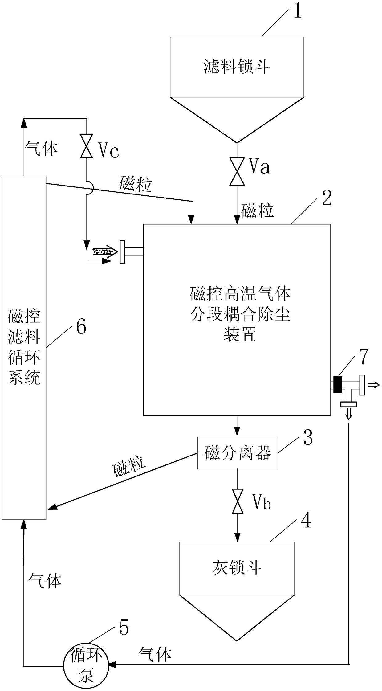
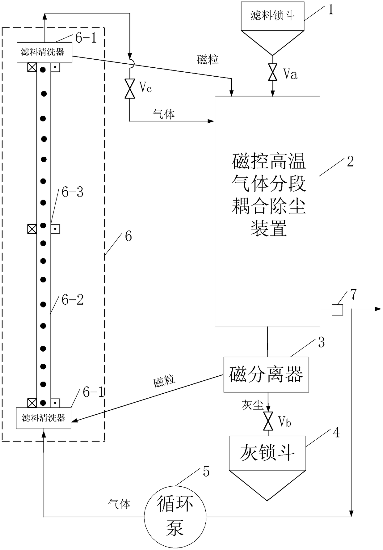
[0055] Specific implementation mode one: see figure 1 Describe this embodiment, a magnetically controlled high-temperature gas segmental coupling dedusting method described in this embodiment, the method is realized based on a segmental coupling dedusting system, and the segmental coupling dedusting system includes a filter material lock hopper 1, Magnetic control high temperature gas segmental coupling dust removal device 2, magnetic separator 3, ash lock bucket 4, circulation pump 5 and magnetic control filter material circulation system 6;

[0056] The discharge port of the filter material lock hopper 1 communicates with the feed port of the magnetically controlled high-temperature gas segmental coupling dedusting device 2, and a valve Va is provided on the discharge pipeline of the filter material lock hopper 1,

[0057] The magnetically controlled high-temperature gas segmental coupling dedusting device 2 uses the filter material particles added by the filter material loc...

specific Embodiment approach 2

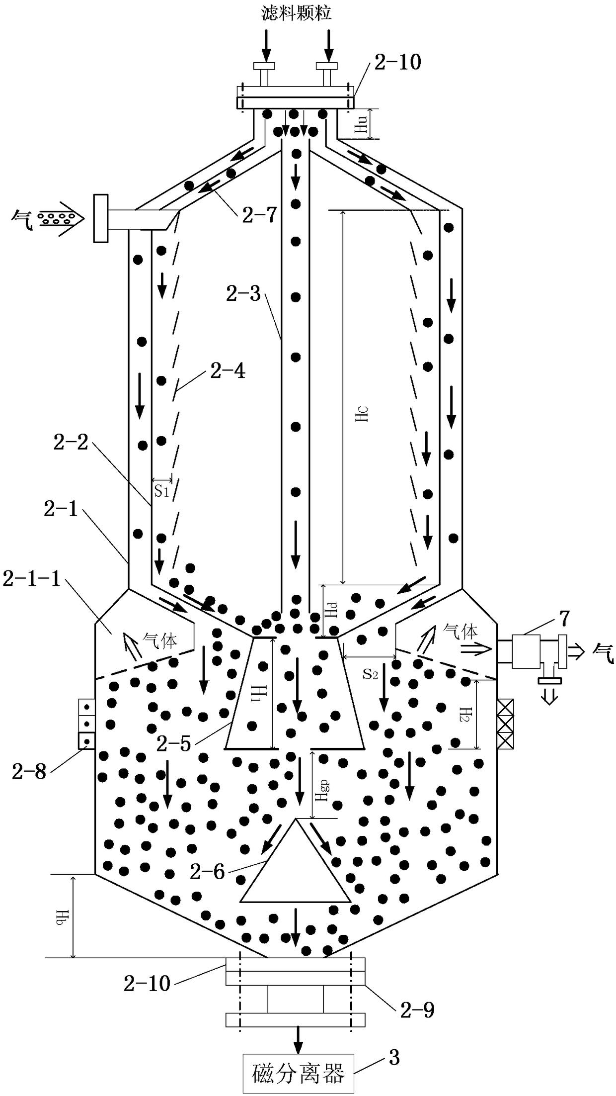
[0070] Specific implementation mode two: see figure 2 Describe this embodiment. The difference between this embodiment and the magnetically controlled high-temperature gas segmental coupling dedusting method described in the first specific embodiment is that the magnetically controlled high-temperature gas segmental coupling dedusting device 2 includes an outer shell 2-1 , inner casing 2-2, center filter particle standpipe 2-3, louver 2-4, buffer cone 2-5, diversion cone 2-6, diversion cone 2-7 and bed control coil 2-8;

[0071] The bed control coil 2-8 is wound on the lower half of the outer casing 2-1, and is used to control the porosity of the filter particles in the outer casing 2-1,

[0072] The inner shell 2-2, the buffer cone 2-5, the diversion cone 2-6 and the diversion cone 2-7 are all located in the outer shell 2-1, and the diversion cone 2-7, the inner The casing 2-2 and the outer casing 2-1 are nested sequentially from the inside to the outside, and there is a c...

specific Embodiment approach 3

[0080] Specific implementation mode three: see figure 1 Or 2 illustrates this embodiment, the difference between this embodiment and a magnetically controlled high-temperature gas segmental coupling dedusting method described in the second embodiment is that the filter material particles have three moving paths:

[0081] First, the filter material particles entering from the channel between the inner shell 2-2 and the outer shell 2-1 move downward and accumulate at the bottom of the outer shell 2-1,

[0082] Second, the filter material particles entering from the channel between the inner shell 2-2 and the diversion cone 2-7 move downward, and flow through the channel between the inner shell 2-2 and the louver 2-4 to the inner shell 2 -2 bottom, so that after passing through the buffer cone 2-5, it is accumulated at the bottom of the outer shell 2-1 after diverted by the diversion cone 2-6,

[0083]Third, the filter material particles entering from the central filter material...


PUM

PropertyMeasurementUnit
particle diameteraaaaaaaaaa

Abstract

The invention provides a magnetic controlled high-temperature gas segmented-coupling dedusting method, and relates to the technical field of high-temperature gas dust removal. The dedusting method solves the problems that the existing high-temperature gas dedusting technology can not realize energy-saving and environment-friendly dust removal, continuous and efficient dust removal as well as economic and reliable dust removal at the same time. The dedusting method comprises the steps of carrying out segmented dedusting on dusty gas by using a magnetic controlled high-temperature gas segmented-coupling dedusting device, recycling the sensible heat of the dedusted gas by using a sensible heat recycling device, and then pumping part of the dedusted gas into a magnetic controlled filter material circulating system serving as circulating gas by means of a circulating pump; using a magnetic separator to carry out magnetic controlled separation on filter material particles and dust particles which are discharged by the magnetic controlled high-temperature gas segmented-coupling dedusting device, feeding the filter material particles separated by the magnetic separator into the magnetic controlled filter material circulating system along an inclined pipeline under the action of gravity, pumping the circulating gas into the circulating system by using the circulating pump for cleaning, ascending and circulating the filter material particles, and sending the cleaned filter material particles into the magnetic controlled high-temperature gas segmented-coupling dedusting device. The magnetic controlled high-temperature gas segmented-coupling dedusting method is suitable for the fields such as combustion, gasification, chemical industry and metallurgy.

Description

technical field [0001] The invention relates to the technical field of high-temperature gas dust removal. Background technique [0002] At present, customers such as pulverized coal gasification and combustion, fluidized bed gasification and combustion, cement kilns, chemical companies, and metallurgical companies have an urgent need for high-performance high-temperature gas dedusting technology without energy-saving, environmental protection, continuous high-efficiency, and economical efficiency. Reliable high temperature gas dedusting technology is available. Traditional high-temperature gas dust removal technology is divided into wet method and dry method. The wet method, especially the Venturi tube dust collector, has the characteristics of continuous high efficiency and reliability, but it consumes a lot of water, has secondary pollution, and the sensible heat of high-temperature gas cannot be recovered, so the energy saving, environmental protection and economy are po...

Claims


Application Information

Patent Timeline
Patent Type & Authority Patents(China)
IPC IPC(8): B01D50/00
CPCB01D50/00Y02P20/10
Inventor 邢春礼赵广播孙锐朱文堃
Owner HARBIN INST OF TECH
Learn More