Multiple-pass corner wire drawing forming method and wire drawing device
A multi-pass, wire-drawing technology, applied in the direction of wire-drawing dies, etc., can solve the problems of insignificant grain refinement effect, single applicable material, complex process, etc., and achieve the effect of good wire-drawing effect, simple operation and simple structure
- Summary
- Abstract
- Description
- Claims
- Application Information
AI Technical Summary
Problems solved by technology
Method used
Image

Examples
Embodiment 1
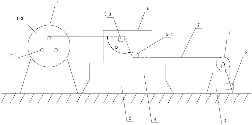
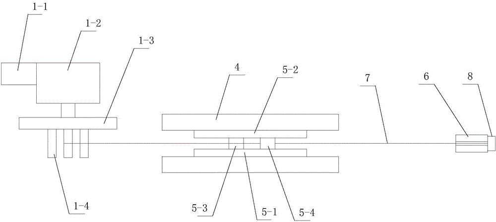
[0032] Such as Figure 1 to Figure 5 As shown, a wire drawing device used in a multi-pass corner wire drawing forming method includes a wire winding device 1 arranged in a straight line, a mold fixing seat 2 and a tailstock 3 .
[0033] The wire winding device 1 includes a driving motor 1-1, a gearbox 1-2, a turntable 1-3 and a winding rod 1-4, the driving motor 1-1 is connected to the gearbox 1-2, and the output shaft of the gearbox is connected to The rotating disk 1-3 is fixed on the rotating disk 1-3 around the screw mandrel 1-4. For the convenience of operation, three winding screw mandrels 1-4 are installed on the rotating disk 1-3, and the three winding screw mandrels 1-4 are located on the same circle with the center of the rotating disk 1-3 as the center.
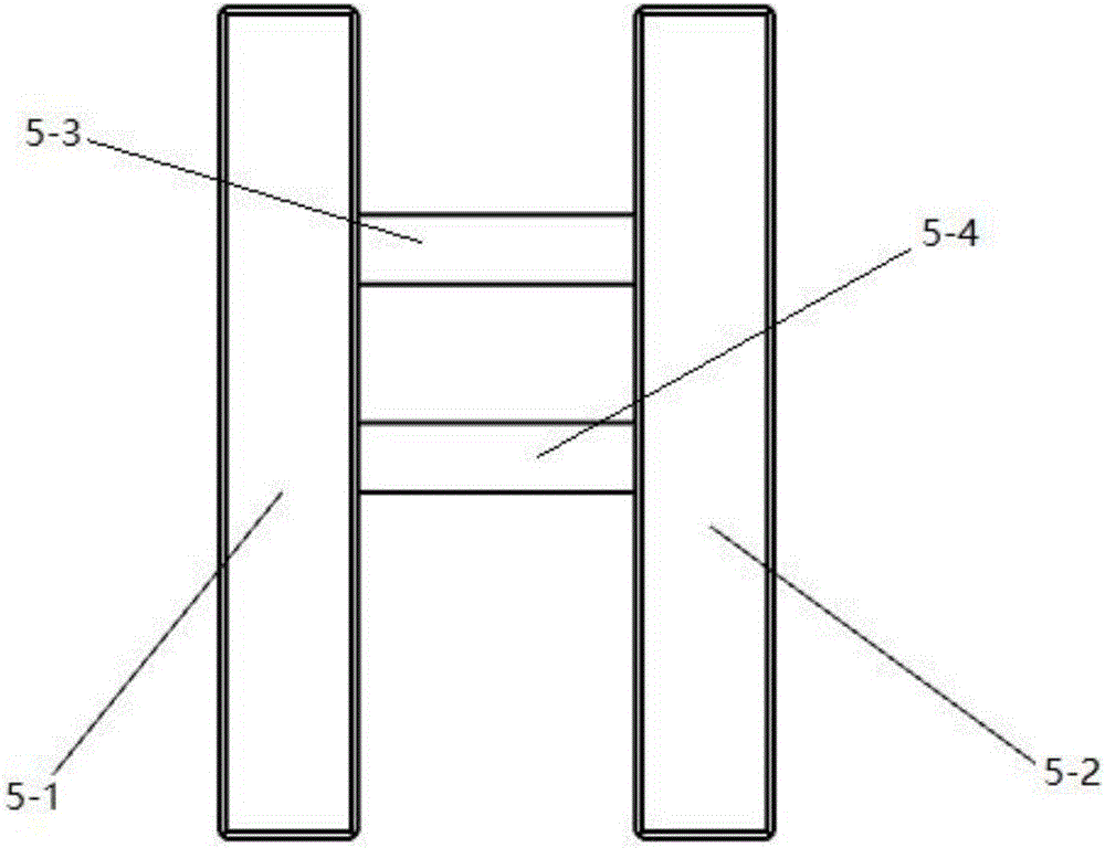
[0034] A clamp mechanism 4 is provided at the top of the mold holder 2 , and the wire drawing die 5 is clamped and fixed by the clamp mechanism 4 . The wire drawing die 5 includes a left fixed plate 5-1, a right ...
Embodiment 2
[0048] see Figure 6 The difference between this embodiment and Embodiment 1 is that the elongated blind grooves 5-5 correspondingly opened on the left and right fixing plates 5-1, 5-2 in the wire drawing device are vertically arranged, and the first forming rod The two ends of 5-3 are movably fitted in the elongated blind groove 5-5, the two ends of the second forming rod 5-4 are fitted in the fixed blind groove 5-6, and the second forming rod 5-4 is located in the first forming One side of the rod 5-3, and the second forming rod 5-4 and the first forming rod 5-3 are parallel to each other.
[0049] In the corresponding wire drawing forming method, the vertical distance between the first forming rod and the second forming rod is adjusted by adjusting the position of the first forming rod in the elongated blind groove.
PUM
| Property | Measurement | Unit |
|---|---|---|
| Diameter | aaaaa | aaaaa |
Abstract
Description
Claims
Application Information
 - R&D
- Intellectual Property
- Life Sciences
- Materials
- Tech Scout
- Unparalleled Data Quality
- Higher Quality Content
- 60% Fewer Hallucinations
Browse by: Latest US Patents, China's latest patents, Technical Efficacy Thesaurus, Application Domain, Technology Topic, Popular Technical Reports.
© 2025 PatSnap. All rights reserved.Legal|Privacy policy|Modern Slavery Act Transparency Statement|Sitemap|About US| Contact US: help@patsnap.com