Laser welding quality monitoring device

A technology of laser welding quality and monitoring device, applied in laser welding equipment, welding equipment, metal processing equipment, etc., can solve the problems of slow welding speed, unsuitable for high-speed production, and high cost

Active Publication Date: 2017-05-10
QINGDAO BRANCH CO., LTD. OF MECHANICAL SCIENCE RESEARCH INSTITUTE
View PDF5 Cites 6 Cited by
  • Summary
  • Abstract
  • Description
  • Claims
  • Application Information

AI Technical Summary

Problems solved by technology

[0002] Laser welding is an efficient and precise welding method that uses a high-energy-density laser beam as a heat source. Laser welding is one of the important aspects of the application of laser material processing technology. Laser welding can be achieved by continuous or pulsed laser beams. The principle of laser welding It can be divided into heat conduction welding and laser deep penetration welding. The power density is less than 104~105 W / cm2 is heat conduction welding. At this time, the penetration depth is shallow and the welding speed is slow; Concave into "holes" to form deep penetration welding, which has the characteristics of fast welding speed and large depth-to-width ratio, so laser welding is widely used in various fields, but at present, most of the inspections of laser-welded products are manual operations. It is necessary to manually compare whether the welding place is qualified, and then classify and place qualified products and unqualified products. This method of detection is inefficient and costly, and is not suitable for modern high-speed production. For this reason, we propose a laser welding Quality monitoring device to solve the above problems

Method used


Image

  • Laser welding quality monitoring device
  • Laser welding quality monitoring device
  • Laser welding quality monitoring device

Examples


Embodiment Construction

[0016] The present invention will be further explained below in conjunction with specific embodiments.

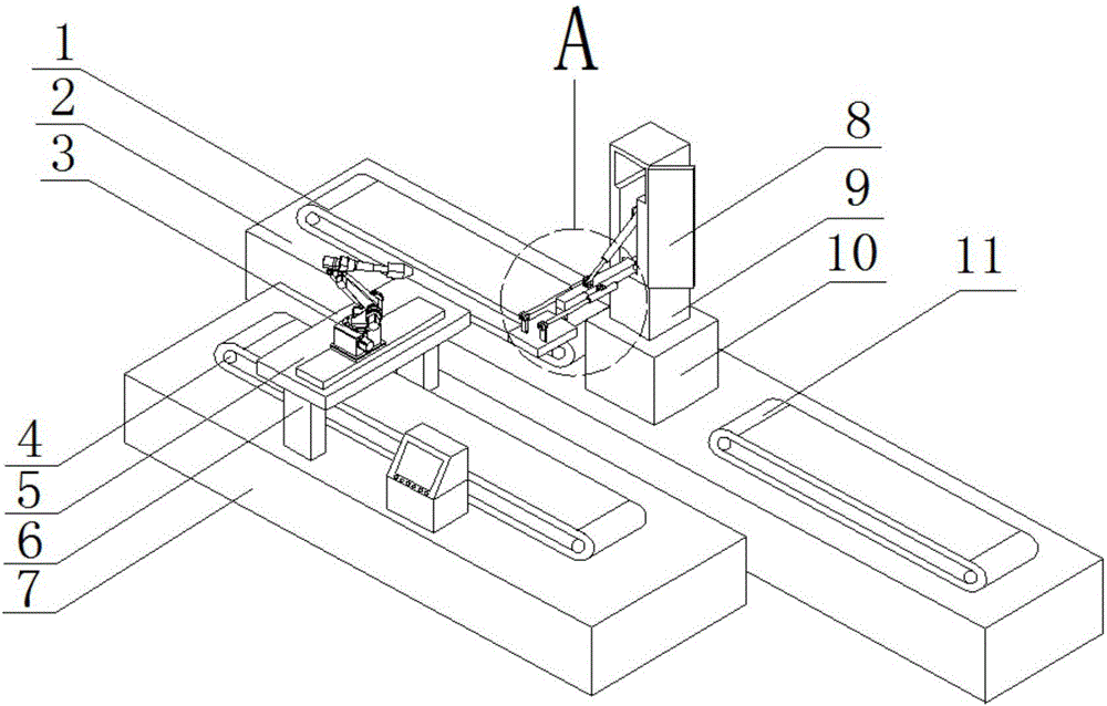
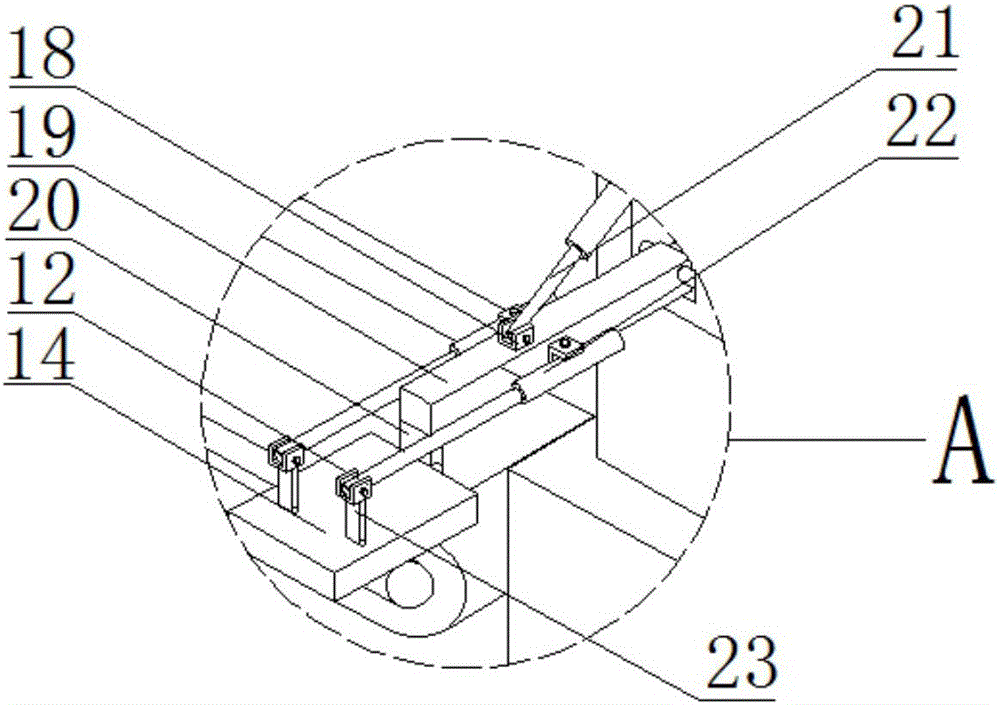
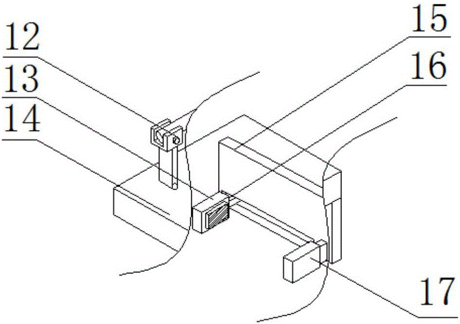
[0017] refer to Figure 1-3 , a laser welding quality monitoring device, comprising two mutually parallel first operating table 7 and a second operating table 2, the first operating table 7 is provided with a first conveyor belt 4 for transporting parts to be welded, the first operating table 7 is provided with a welding device, and the parts to be welded are transferred to the lower end of the welding device through the first conveyor belt 4 for welding, and the upper end side of the second operating table 7 is provided with a second conveyor belt 1 for transporting unqualified parts for welding. The other side of the upper end of the platform 7 is provided with a third conveyor belt 11 for conveying welding qualified parts, and a carrying platform 10 is provided between the second conveyor belt 1 and the third conveyor belt 11, and the lower end of the carrying platform 1...


PUM


Abstract

The invention discloses a laser welding quality monitoring device comprising a first operating platform and a second operating platform parallel to each other. A first conveying belt used for conveying a part to be welded is arranged on the first operating platform. A welding device is arranged on the first operating platform. A second conveying belt used for conveying an unqualified welded part is arranged on one side of the upper end of the second operating platform. A third conveying belt used for conveying a qualified welded part is arranged on the other side of the upper end of the second operating platform. A bearing platform is arranged between the second conveying belt and the third conveying belt, and the lower end of the bearing platform is fixed on the second operating platform. Through the combination of the multiple conveying belts, a welding robot, an electric sliding rail and the like, automatic welding and conveying of the part are achieved. An automatic transfer is achieved through the arrangement of a transfer device. Automatic identifying and clamping are achieved through the combination of a visual sensor and a clamping device. Not only is the labor cost reduced, but also the production efficiency is improved, and the laser welding quality monitoring device is suitable for being popularized.

Description

technical field [0001] The invention relates to the field of laser welding, in particular to a laser welding quality monitoring device. Background technique [0002] Laser welding is an efficient and precise welding method that uses a high-energy-density laser beam as a heat source. Laser welding is one of the important aspects of the application of laser material processing technology. Laser welding can be achieved by continuous or pulsed laser beams. The principle of laser welding It can be divided into heat conduction welding and laser deep penetration welding. The power density is less than 104~105 W / cm2 is heat conduction welding. At this time, the penetration depth is shallow and the welding speed is slow; Concave into "holes" to form deep penetration welding, which has the characteristics of fast welding speed and large depth-to-width ratio, so laser welding is widely used in various fields, but at present, most of the inspections of laser-welded products are manual o...

Claims


Application Information

Patent Timeline
Patent Type & Authority Applications(China)
IPC IPC(8): B23K31/12B23K26/70
CPCB23K26/70B23K31/125
Inventor 冯庆柱王西峰
Owner QINGDAO BRANCH CO., LTD. OF MECHANICAL SCIENCE RESEARCH INSTITUTE
Why Eureka
Try Eureka